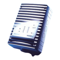
Installation TITANUS MICRO·SENS
®
5 – 10 Data: 01/09 MS_A_05-en-e
5.5 Incorporating the reset board
The reset board can be used as an option for the TITANUS
MICRO·SENS
®
. The reset board is mounted in an additional housing. If
several TITANUS MICRO·SENS
®
are connected to a detection line, then
the reset board is only connected into the detection line after the last
TITANUS MICRO·SENS
®
. The electrical connection to the reset board is
as per the switching plan (see Fig. 5.10).
The reset board can only be used if the idling current on the detection
line is between 5 mA and 50 mA and the detection line terminal has an
ohmic resistance. The reset impulse is triggered if the line voltage falls
below 3V when the central unit is reset.
Line idling current The idling current I
R
on the line is calculated as follows:
E
L
R
R
U
I =
where R
E
= Original terminating resistor of the line in [
Ω
]
U
L
= Line voltage in [V]
I
R
= Idle current on the line in [A]
The formulae shown for calculating the terminating resistor and the idling
current on the detection line take account of the ideal status for signal
evaluation.
If no acknowledgement is given from calculating the reset board
terminating resistor, the value of the terminating resistor must be reduced
by about 20 %.
Terminating resistor The reset board balances the detection line terminating resistor. It is
calculated afresh and incorporated in the reset board (Connection X1,
see Fig. 5.10). The value of the terminating resistor R
ER
is calculated as
follows:
()
R
L
ER
I
VU
R
7,2−
=
where R
ER
= Terminating resistor on the reset board in [
Ω
]
U
L
= Line voltage in [V]
I
R = Idling current on the line in [A]
INSTRUCTION

 Loading...