Installation TITANUS MICRO·SENS
®
5 – 26 Data: 01/09 MS_A_05-en-e
5.10.2 Parallel display housing
Fitting the front film
Cable entry
Front film
Cable entry
Cable entry
Cable entry
Parallel display unit
in wall housing
(optional)
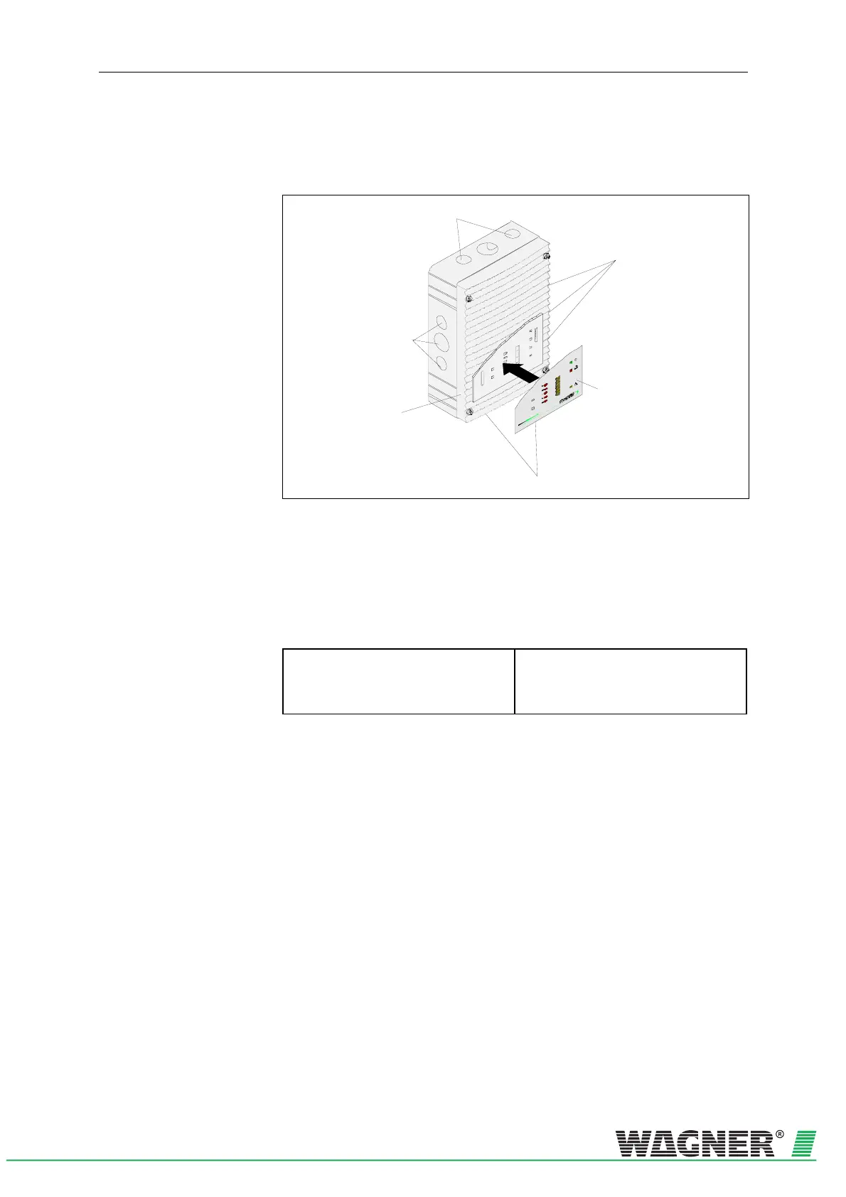
Fig. 5.24: Fitting the front film for the parallel display
With the parallel display the cable entry can be above, below or at the
side without the cover having to be turned. The switching power supply
for the parallel display is fitted to the installation plate of the parallel dis-
play housing
(for fixing points see Fig. 5.8).
Wall fixing The device base unit for a parallel display is screwed directly onto a wall.
Installation equipment
Parallel display
Cylinder or flat head screws
– Thread diameter: max. 4 mm
– Head diameter: max. 8 mm
Hole distances The drilling template is shown in the Fig. 5.3 (all dimensions in mm).