Pipe Design TITANUS MICRO·SENS
®
4 – 28 Data: 01/09 MS_A_04-en-e
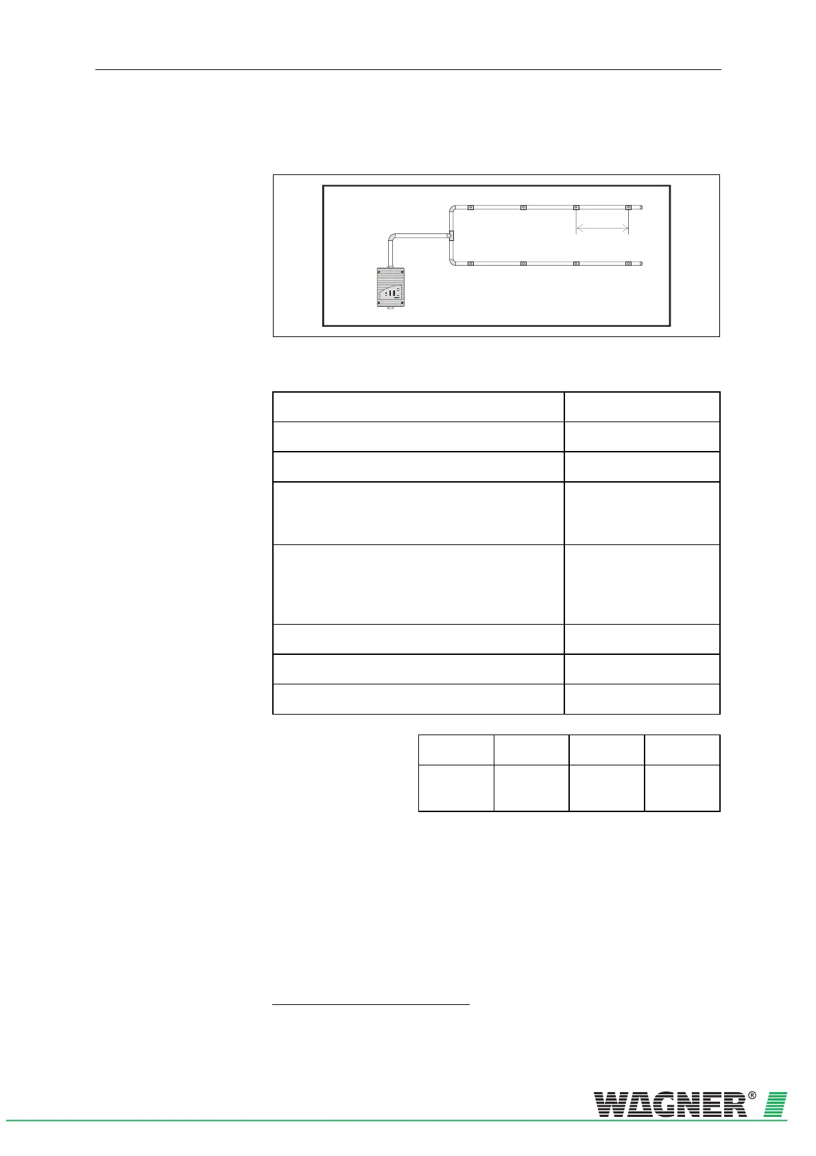
4.3.2.2 U-pipe system
1 Pipe system
TITANUS
MICRO·SENS
P
®
P
d
TITANUS MICRO·SENS
®
E
D
C
B
A
10
9
8
7
6
5
4
3
2
1
TITANUS
®
Fig. 4. 11: U-pipe system, e.g. for equipment protection
Limit values
min. distance TITANUSP
®
P
– T piece 2 m
max. distance TITANUSP
®
P
– T piece 20 m
max. branch length 25 m
max. overall pipe length per pipe system
Pipe ∅ 25 mm plus
pipe ∅ 12 mm
50 m
8 x 3 m
max. overall pipe length per pipe system with a ventila-
tor voltage of <10.5 V
Pipe ∅ 25 mm plus
pipe ∅ 12 mm
40 m
8 x 3 m
max. number of aspiration apertures (n) per pipe system 8 no.
minimum distance between the aspiration apertures (d) 0,1 m
maximum distance between the aspiration apertures (d) 4 m
Aspiration apertures
Number of apertures 2 4 6 8
∅ of all aspiration
apertures in mm
TP15F
16
PT) 6,0 4,2 3,4 3,0
TP
16
PT Opening diameter of the aspiration reduction film