Pipe Design TITANUS MICRO·SENS
®
4 – 32 Data: 01/09 MS_A_04-en-e
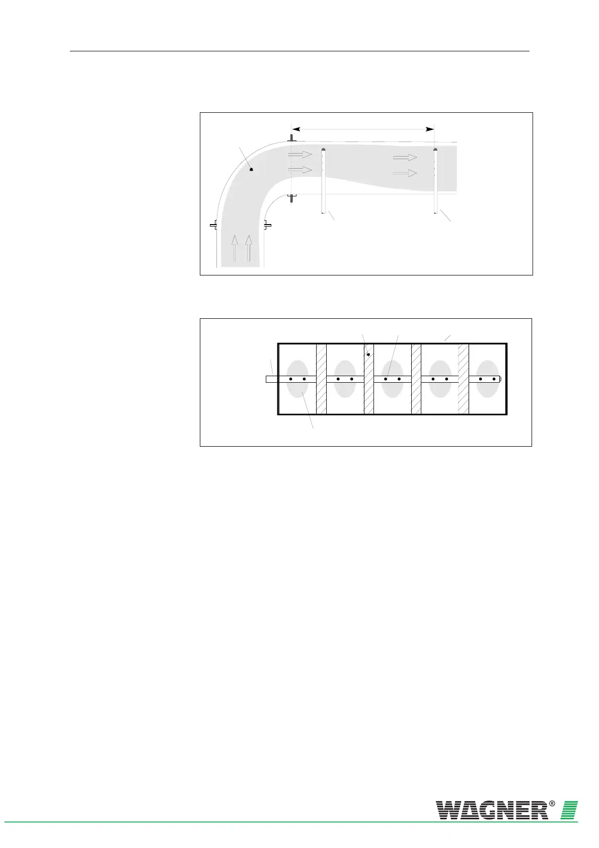
Main speed area
Pipe system
arrangement in exceptional case
(if the distance 3x smallest
duct diameter can not be maintained)
Standard pipe system
Min. 3 x smallest duct diameter
Fig. 4.15: Duct direction change without baffle plates
Sound damping
Main speed area
Hole
Air sampling pipe
Air conditioning duct
Fig. 4.16: Sound dampers in a duct
When a pipe system is built into air conditioning ducts, the following must
be observed:
• As the TITANUS MICRO·SENS
®
P
and the pipe system are in
different pressure areas, there must be an air return arrangement
(see following page).
• The pipe entries into the duct must be sealed air-tight.
• The part of the pipe system which is outside the duct must be
bonded air-tight.
 Loading...


