Installation TITANUS MICRO·SENS
®
5 – 24 Data: 01/09 MS_A_05-en-e
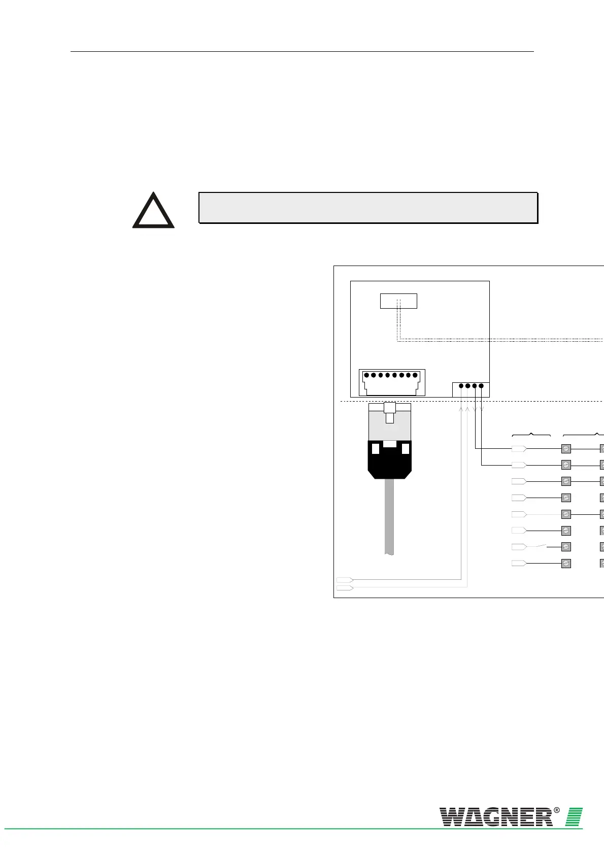
5.9.2 Connecting the Network Module
The network module creates the connection between the bus system and
the TITANUS MICRO·SENS
®
. Fig. 5.22 shows the electrical switching
plan which must be followed for this in the aspirating smoke detector.
To operate the TITANUS MICRO·SENS
®
in a network, more information
is needed about the bus system and the PC software.
Faul t
Faul t
Reset+
Reset-
L1-
L1+
1a
2a
3a
4a
5a
6a
7a
8a
1
in terna l conne ctio
Connection to outside central unit
Network module
X1
X5
- Ub
+ Ub
0V
+24V
- Ub
+ Ub
132 45678
RJ45-Socket
- TD
- RD
+ TD
+ RD
Network cable KAT 5
1324
X4
RJ45-Plug
(shielded)
+24V
0V
dditional hou
Housing base detectio
Fig. 5.22: Connecting the network board
INSTRUCTION