Installation TITANUS MICRO·SENS
®
5 – 22 Data: 01/09 MS_A_05-en-e
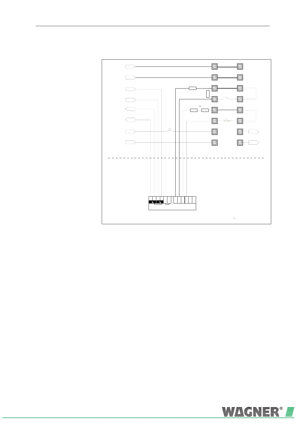
5.8.3.3 TITANUS MICRO·SENS
®
and interactive technology
Reset-
button
Reset +
Reset -
L1-
L+
0V
1a
2a
3a
4a
5a
6a
7a
8a
1b
2b
3b
4b
5b
6b
7b
8b
+24V
Indicator bus
Interactive line
from central unit
L -
L+
1) Detectio n line 1: Working co ntact monito red fo r
interruption and short circuit
Detectio n line 2: Idling contact mo nitored f or
interruption and short circuit.
Software can be parametrise
via central unit
2) Connection : m ax 1,5 mm
2
Interactive Line
to central unit or to
input component
DC 1157-AA of the
next dev ice
Inpu t comp on en t DC 1157- AA in teractiv
- +
Z M2L1 M1 L2 L3 M3Z
-+
Detection line
2)
1)
24V D C
1k87
4k75
4k751k87
3) Alternative : 1 x 6K8 R esistance
Additional housing
Device Base detection unit
Fig. 5.20: Connection in interactive technology

 Loading...

