TITANUS MICRO·SENS
®
Installation
MS_A_05-en-e Data: 01/09 5 – 21
Also comply with the installation instructions enclosed with each line
component.
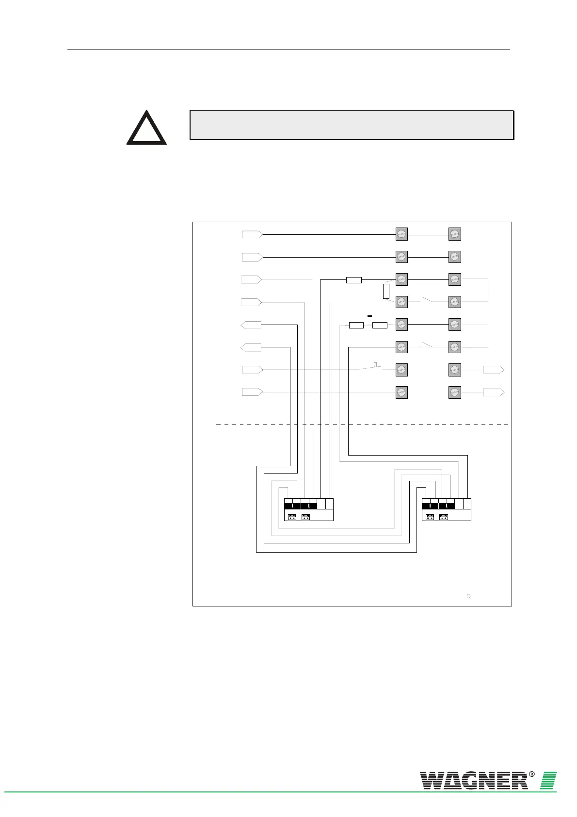
5.8.3.2 TITANUS MICRO·SENS
®
and AnalogPLUS technology
Reset +
Reset -
L1-
L+
0V
1a
2a
3a
4a
5a
6a
7a
8a
1b
2b
3b
4b
5b
6b
7b
8b
+ 24V
Indicator bus
1) D etection line monitored fo r
interruption and short circuit
2) Connection: m ax 1,5m m
2
LM
X19 X18
Jum per
1)
2)
Input component
(Mai n al arm)
DC1131-31
AnalogPLUS
®
-+-+
AnalogP LUS -Line from
central unit
1k87
4k75
LM
X19 X18
Ju m pe r
1)
2)
input component
(Fault)
DC1131-31
AnalogPLUS
®
-+-+
L-
L+
24V D C
4k751k87
3) Alternative : 1 x 6K8 -Resistance
Additional housing
Device Base detection unit
Reset button
AnalogPLUS-Line to
central unit or to input
component DC 1131-31
of the next device
Fig. 5.19: Connection in AnalogPlus technology
INSTRUCTION

 Loading...

