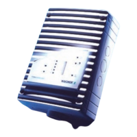
Commissioning TITANUS MICRO·SENS
®
7 – 14 Data: 01/09 MS_A_07-en-e
4. After initialising, close the 4.2 mm aspiration hole on the test pipe
with some sticky tape. After about 5 secs, the fault display on the
device must start to flash. After about 35 secs, the fault display on
the device must be permanently on. The device signals the fault
“Air flow too low (statistical evaluation)“. The air flow figure is about
–35 %.
5. Open the 4.2 mm aspiration hole again. After a few seconds, the
fault display on the TITANUS MICRO·SENS
®
must stop flashing.
6. Open the 7.0 mm aspiration pipe on the test pipe. After about 5 secs
the fault display on the device must start to flash. After about
35 secs, the fault display on the device must be permanently on. The
device signals the fault “Air flow too high (statistical evaluation)“. The
air flow figure is about +85 %.
7. Close the 7.0 mm aspiration hole again. The fault display on the
TITANUS MICRO·SENS
®
must stop flashing after a few seconds.
8. Remove the test pipe and re-connect the pipe system.
After function tests are completed, the original settings must be restored.
Commissioning the TITANUS MICRO·SENS
®
is to be repeated from
Chapter 7.3 “Air Flow Sensor Adjustment“.
Connection testing Test whether ...
1. The pipe system is firmly connected to the TITANUS MICRO·SENS
®
pipe
connection.
2. All pipe fittings are glued and the pipe system is sealed tight. For this, first
close all aspiration apertures (e.g. with insulating tape). Using a flow
measurement device, measure the air flow at the aperture for the air flow
return.
3. The correct aspiration reducing films have been stuck to the aspiration
apertures.
After the air flow sensor is adjusted (Chapter 7.3 "Air Flow Sensor
Adjustment ") no more changes should be made to the pipe system.
If changes are necessary later, the air flow sensor must be
adjusted again.
After function tests are completed, the device and the pipe system must
be re-commissioned from Chapter 7.3 "Air Flow Sensor Adjustment".
After commissioning is completed, the settings should be recorded using
the diagnosis tool and stored. A print-out of the settings should be filed
with the project documents for subsequent follow-up work.
INSTRUCTION
INSTRUCTION

 Loading...