Installing the GC interface 6-5
8. Remove the 1/4-inch graphitized Vespel ferrule by cutting part of it
away with wire cutting pliers.
Requirement: If the 1/4-inch ferrule has been removed by cutting,
replace it.
9. Ensure the spring-loaded tip has maximum travel when compressed. If
required, the compression spring can be carefully stretched to allow
maximum movement.
GC interface tip:
Note: If the GC interface has not been previously fitted to the
instrument, the interface fitting tool is secured to the interface flange by
two thumbscrews. In this case, follow the procedure described in
Working with the interface fitting tool on page 6-6.
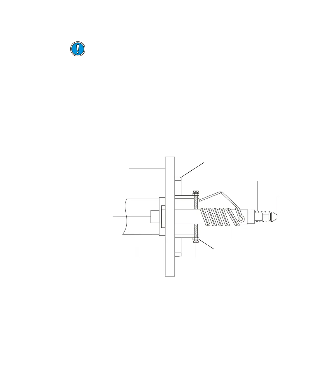
10. Ensure that the Viton O-ring is in the groove in the GC interface flange.
Caution: Be careful not to damage the transfer line shaft when
removing the graphitized Vespel ferrule with wire cutting pliers.
Doing so can cause air leaks.
Locating ring
Interface flange
eater connection
Interface body Adjustment screw
Lock nut
Heater tube
Compression spring
Tip