ENGINE
M6060, M7060, WSM
1-M16
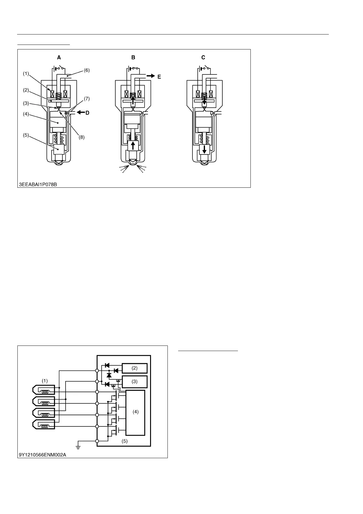
Injector Operation
The injector uses the signal output from the engine ECU to control the injection with the fuel pressure in the control
chamber.
The system for controlling the pressure of the control chamber works by energizing the solenoid, which opens the
passage of the chamber's discharge orifice and the fuel is injected due to the drop in pressure. When the current
stops, the pressure in the control chamber returns to what it was and injection ceases.
1) Injection Stop
With no current to the solenoid (1), the TWV (2) cuts off the discharge orifice (3) passage, so rail pressure is
applied to the control chamber (8) and the bottom of the needle valve (5). As the diameter of the command piston (4)
on the control chamber side is larger than the diameter of the bottom of the needle valve, it works to push the needle
valve down, which is compounded by the nozzle spring pushing it down, and the needle valve is closed.
2) Injection Start
When the solenoid (1) is energized, it draws the TWV (2) up, opening the passage of the discharge orifice (3),
returning fuel in the control chamber (8) to the fuel tank via the leak passage (6) and dropping the pressure.
The drop in the pressure of the control chamber causes the pressure applied to the bottom of the needle valve
(5) to become greater than the pressure on the control chamber side, and the needle valve compresses the nozzle
spring and starts injecting fuel.
3) Injection Finish
When current to the solenoid (1) stops, the TWV (2) lowers and the discharge orifice (3) passage is closed.
When the passage of the discharge orifice closes, the fuel pressure in the control chamber (8) recovers to the rail
pressure, so the needle valve (5) is pressed back via the command piston (4), stopping the injection.
9Y1210828ENM0025US0
Injector Drive Circuit
To increase the responsiveness of the injector, the
voltage that drives the injector is raised to a high voltage,
accelerating the magnetization of the solenoid and
increasing the responsiveness of the TWV.
The battery voltage is raised to about 110 V by a
high-voltage generating circuit inside the ECU and that
voltage is supplied to the injector to actuate it.
9Y1210828ENM0026US0
(1) Solenoid
(2) TWV (Two-way Valve)
(3) Discharge Orifice
(4) Command Piston
(5) Needle Valve
(6) Leak Passage
(7) Intake Orifice
(8) Control Chamber
A: Injection Stop
B: Injection Start
C: Injection Finish
D: From Rail
E: To Fuel Tank
(1) Injector
(2) Rated Amperage Circuit
(3) High-voltage Generating
Circuit
(4) Control Circuit
(5) Engine ECU