ENGINE
M6060, M7060, WSM
1-S50
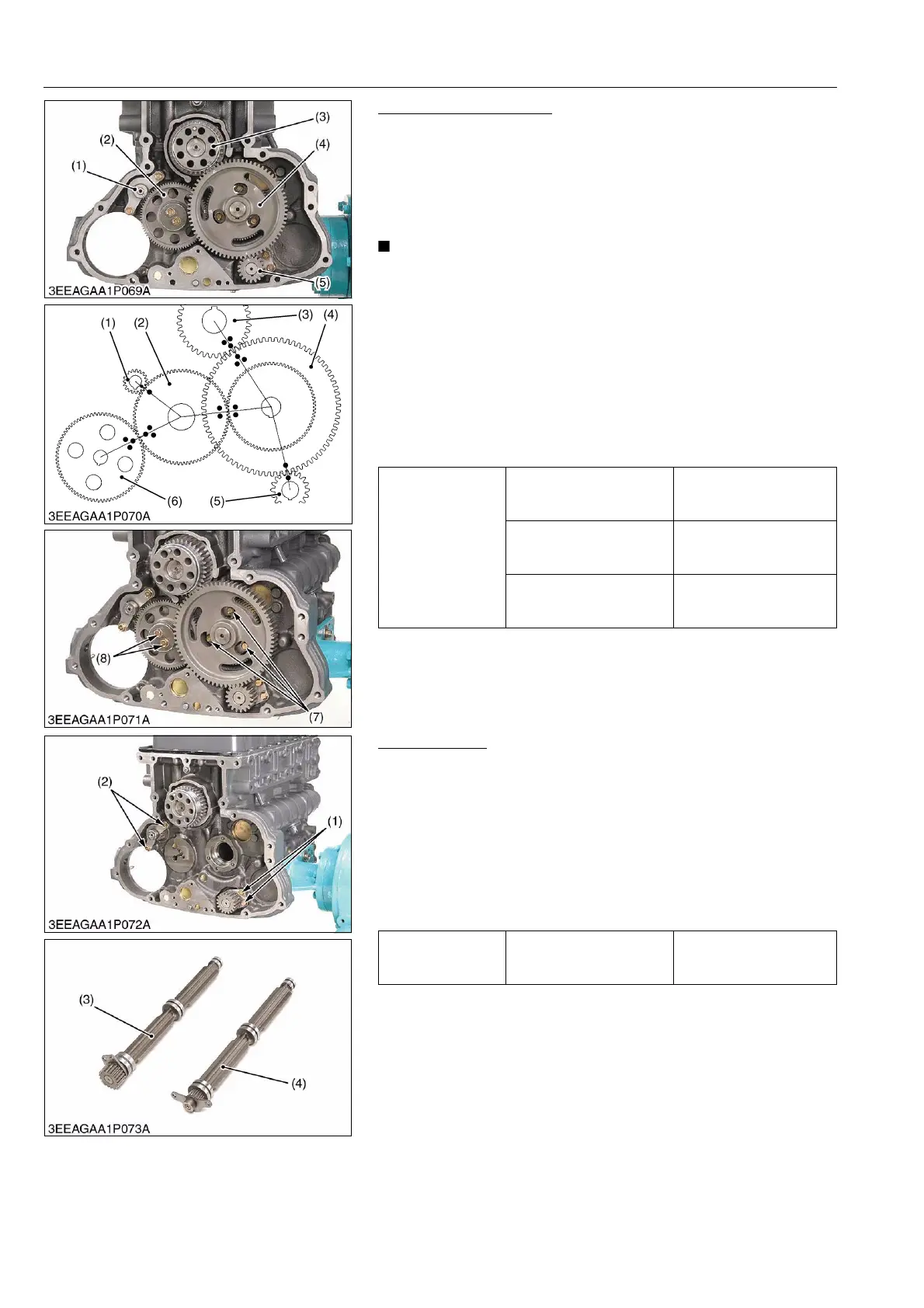
Camshaft and Idle Gear
1. Rotate the cylinder head side of the engine crankcase to the
lower side.
2. Remove three set screws of the camshaft holder (7) and draw
out the camshaft.
3. Remove the idle gear mounting screws (8) and draw out the idle
gear.
• If the cylinder head side of the engine crankcase does not
become lower side, the tappets drop and become the
trouble to the camshaft. The camshaft will not be able to be
drawn out.
(When reassembling)
• When installing the idle gear (2) and cam gear (4), be sure to
place the 4th cylinder piston at the top dead center in
compression then, align all mating marks on each gear to
assemble the timing gears, set the cam gear last.
• Mount the injection pump gear (6) after installing the flywheel
housing.
9Y1210828ENS0069US0
Balancer Shaft
1. Remove the balancer shaft 1 set screws (1) and draw out the
balancer shaft 1 (3).
2. Remove the balancer shaft 2 set screws (2) and draw out the
balancer shaft 2 (4).
(When reassembling)
• When installing the balancer shaft 1 (3) and 2 (4), be sure to
place the 4th cylinders piston at the top dead center in
compression then, align all mating marks on each gear to
assemble the timing gears, set the cam gear last.
9Y1210828ENS0070US0
Tightening torque
Camshaft set screw
23.5 to 27.5 N·m
2.4 to 2.8 kgf·m
17.3 to 20.3 lbf·ft
Idle gear mounting screw
(7T)
23.5 to 27.5 N·m
2.4 to 2.8 kgf·m
17.3 to 20.3 lbf·ft
Idle gear mounting screw
(10T)
30 to 35 N·m
3.0 to 3.5 kgf·m
22 to 25 lbf·ft
(1) Balancer 2 Gear
(2) Idle Gear
(3) Crank Gear
(4) Cam Gear
(5) Balancer 1 Gear
(6) Injection Pump Gear
(7) Camshaft Set Screw
(8) Idle Gear Mounting Screw
Tightening torque Balancer shaft set screw
23.5 to 27.5 N·m
2.4 to 2.8 kgf·m
17.3 to 20.3 lbf·ft
(1) Balancer Shaft 1 Set Screw
(2) Balancer Shaft 2 Set Screw
(3) Balancer Shaft 1
(4) Balancer Shaft 2