FRONT AXLE
M6060, M7060, WSM
5-S15
Backlash and Tooth Contact between Bevel Pinion Shaft and
Bevel Gear
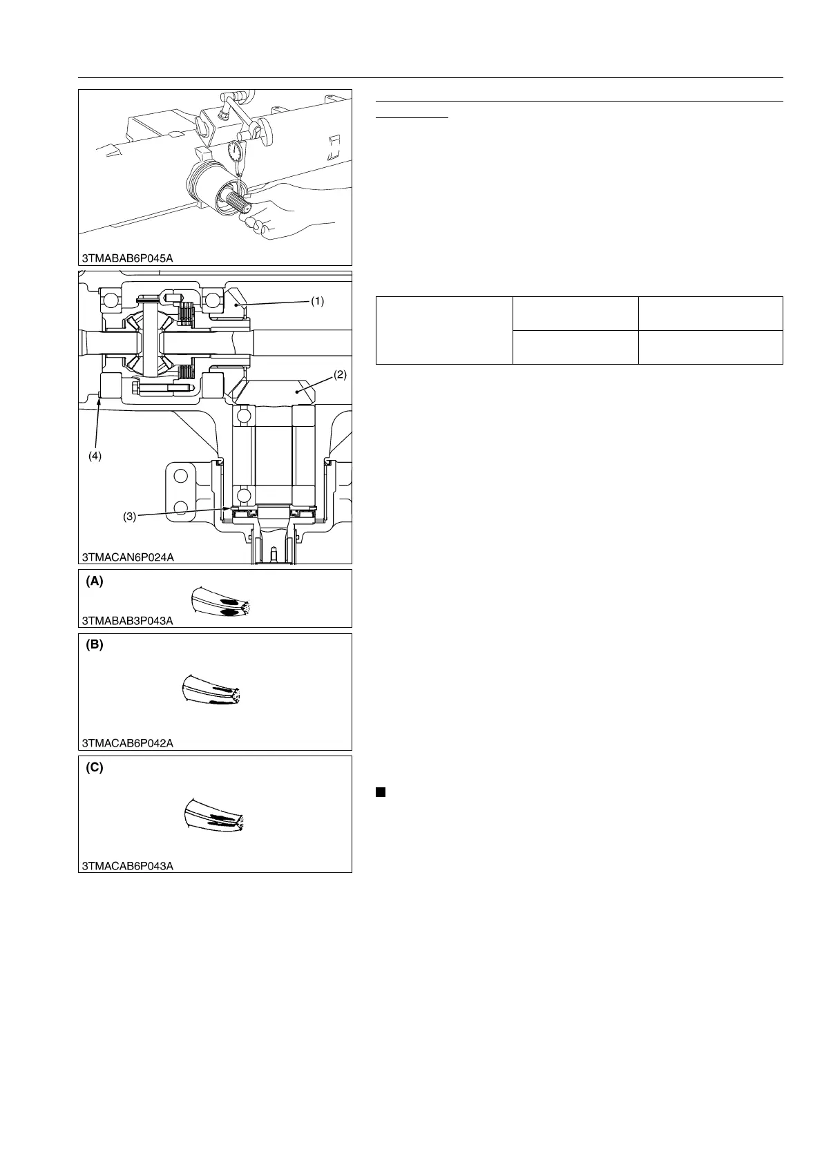
1. Set a dial indicator (lever type) with its finger on the tooth
surface.
2. Measure the backlash by fixing the bevel pinion shaft (2) and
moving the bevel gear (1) by hand.
3. Calculate the backlash from the ratio of the shaft diameter to the
gear diameter. (Backlash = Play × 2.7)
4. If the backlash exceeds the allowable limit, adjust with the shim
(4).
5. Adjust the backlash properly by repeating the above
procedures.
6. Apply red lead lightly over several teeth at three positions
equally spaced on the bevel gear (1).
7. Turn the bevel pinion shaft (2), against the periphery of the
bevel gear.
8. Check the tooth contact. If not proper, adjust according to the
instructions shown in the figure.
(Reference)
• Thickness of adjusting shims (3) :
0.1 mm (0.004 in.) [Code No.: 35533-44080]
0.2 mm (0.008 in.) [Code No.: 35533-44090]
0.4 mm (0.016 in.) [Code No.: 35533-44100]
0.8 mm (0.032 in.) [Code No.: 35533-44110]
1.0 mm (0.039 in.) [Code No.: 35533-44120]
1.2 mm (0.047 in.) [Code No.: 35533-44130]
• Thickness of adjusting shims (4) :
0.7 mm (0.028 in.) [Code No.: 3A151-32180]
0.8 mm (0.032 in.) [Code No.: 3A151-32130]
1.0 mm (0.039 in.) [Code No.: 3A151-32140]
1.2 mm (0.047 in.) [Code No.: 3A151-32150]
1.4 mm (0.551 in.) [Code No.: 3A151-32160]
2.3 mm (0.091 in.) [Code No.: 3A151-32170]
• Standard size of shim (3) : 0.5 mm (0.020 in.)
Standard size of shim (4) : 1.2 mm (0.047 in.)
• Backlash changes per 0.1 mm (0.004 in.) shim :
Approx. 0.05 mm (0.002 in.)
• Adjust the tooth contact with shims (3) and (4) so that the
spiral bevel pinion shaft may not contact with the
differential case.
9Y1210828FAS0025US0
Backlash between bevel
gear and bevel pinion
shaft
Factory specification
0.20 to 0.30 mm
0.0079 to 0.011 in.
Allowable limit
0.4 mm
0.02 in.
(1) Bevel Gear
(2) Bevel Pinion Shaft
(3) Shim
(4) Shim
(A) Proper Contact :
More than 35 % red lead contact
area on the gear tooth surface.
The center of tooth contact at 1/3
of the entire width from the small
end.
(B) Deep Contact :
Decrease the shims.
(C) Shallow Contact :
Increase the shims.