HYDRAULIC SYSTEM
M6060, M7060, WSM
7-S13
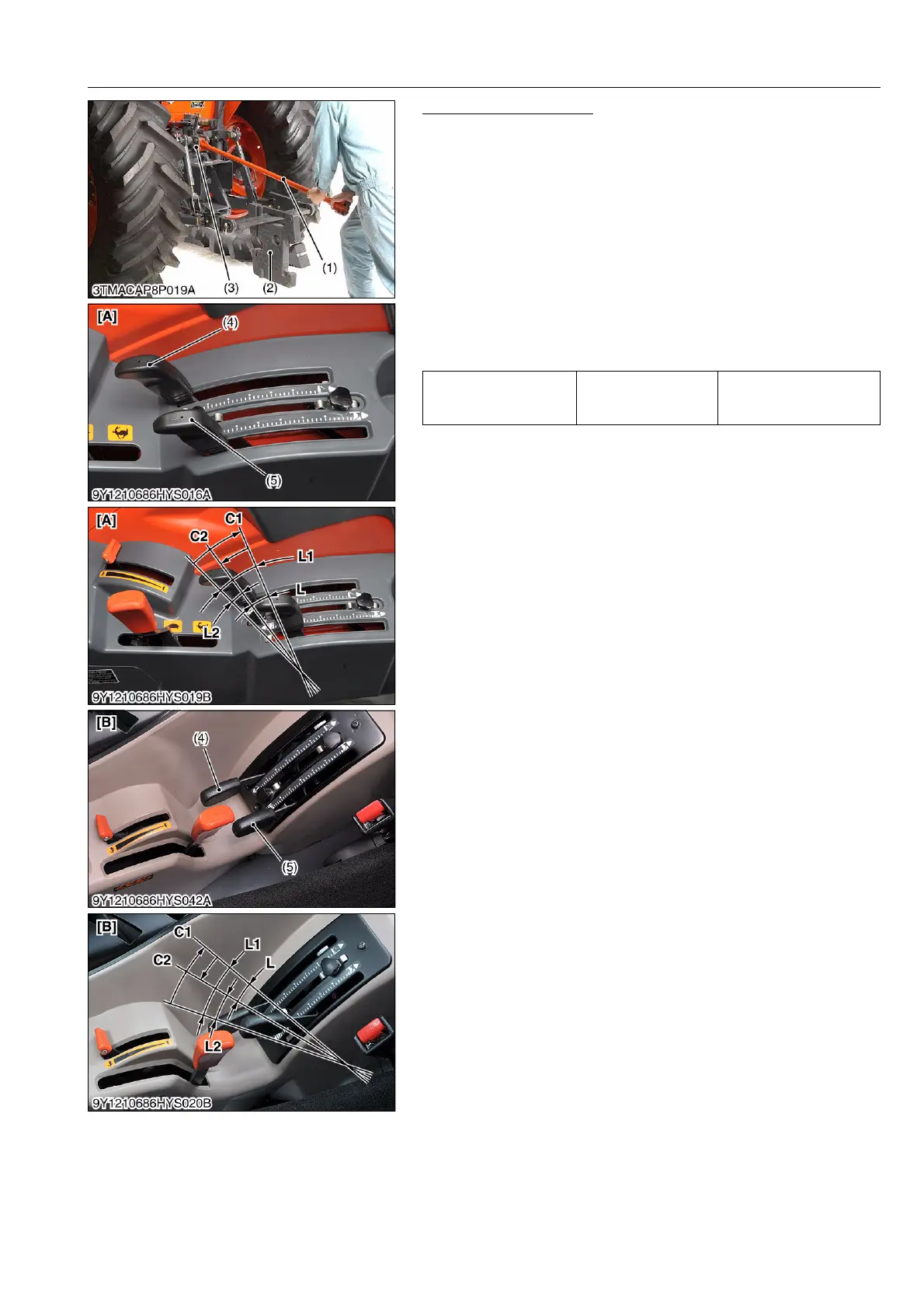
Draft Lever Free Range
1. Attach the weight (2) of approx. 490 N (50 kgf, 110 lbf) to the
end of the lower links.
2. Attach the test bar (1) (see page G-81) to the top link bracket
(3).
3. Start the engine and set the engine speed at maximum speed.
4. Move the draft and position control lever (5), (4) all the way
down.
5. Press the test bar (1) downward until the top link bracket (3)
comes in contact with the body.
6. Slowly shift the draft control lever (5) upward until the lift arms
begin to rise (C1). Then slowly shift the draft control lever (5)
downward until the lift arms begin to down (C2). Calculate the
free range (L) of the draft control lever (5) on the lever guide.
9Y1210828HYS0011US0
Free range L1 – L2 Factory specification
Less than
25.0 mm
0.984 in.
(1) Test Bar
(2) Weight
(3) Top Link Bracket
(4) Position Control Lever
(5) Draft Control Lever
[A] ROPS Model
[B] CABIN Model
C1 : Begin to rise the lift arm
C2 : Begin to down the lift arm
L : Free Range
L1 : Distance for begin to rise the lift
arm
L2 : Distance for begin to down the lift
arm
 Loading...
