ELECTRICAL SYSTEM
M6060, M7060, WSM
8-S38
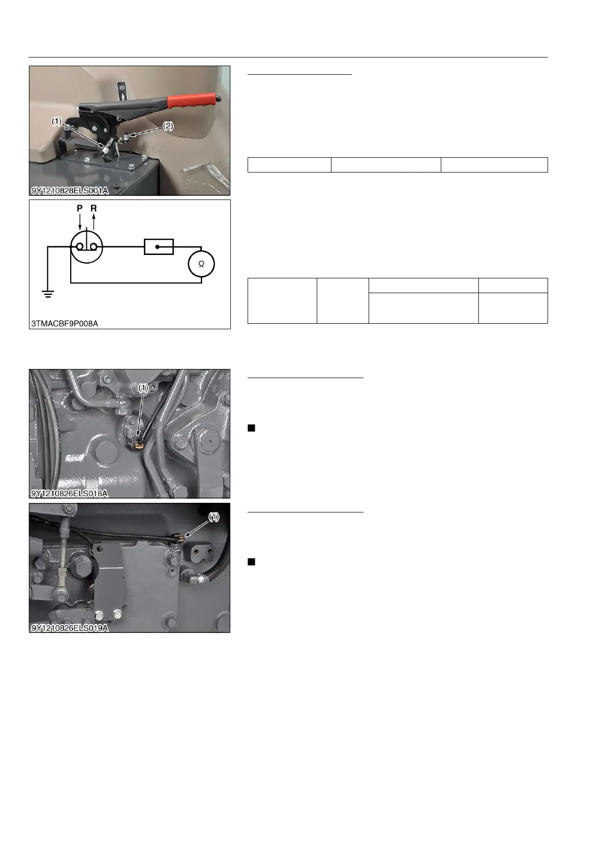
Parking Brake Switch
1) Connector Voltage
1. Remove the connector (1).
2. Turn the main switch ON position.
3. Measure the voltage across the terminal and chassis.
4. If the voltage differs from battery voltage, the wiring harness,
fuse, or main switch is faulty.
2) Parking Brake Switch Continuity
1. Remove the parking brake switch (2).
2. Check the continuity with an ohmmeter across the switch
terminal and chassis.
3. If it does not conduct or any value is indicated when the switch
is released, the switch is faulty.
4. If infinity is not indicated when the switch is pushed, the switch
is faulty.
9Y1210828ELS0061US0
Traveling Speed Sensor
1. Check traveling speed display.
2. If it is OK, the engine speed is displayed in the meter panel.
3. If it is OK, the traveling speed is displayed in the LCD monitor.
• As for engine speed sensor and traveling speed sensor are
not checking with circuit tester.
9Y1210828ELS0062US0
Shuttle Rotation Sensor
1. Check the meter panel.
2. If the shuttle rotation sensor (1) is detected, [ERROR-23] is
displayed in meter panel.
• As for shuttle rotation sensor is not checking with circuit
tester.
9Y1210828ELS0063US0
Voltage Terminal – Chassis Approx. battery voltage
Resistance
(Across switch
terminal and
chassis)
Reference
value
When switch is pushed Infinity
When switch is released 0 Ω
(1) Connector
(2) Parking Brake Switch
P: Pushed
R: Released
(1) Traveling Speed Sensor
(1) Shuttle Rotation Sensor