270
3)Suitable soft components
*Notes: D includes D, HD; TD includes TD, HTD; CD includes CD, HCD, HSCD, HSD; DM
includes DM, DHM; DS includes DS, DHS. M includes M,HM,SM;S includes S,HS;T
includes T,HT;C includes C, HC.
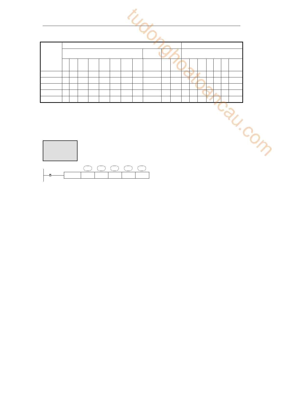
MRGW K1 K500 K3 D1
X0
K2
D1· D2· D3· S1· S2·
Write multiple registers, Modbus function code is 10H.
Serial port: K0~K5. K0: Port0 (RS232), K1: Port1(RS232), K2: Port2(RS485), K3:
Port3(left extension port), K4: Port4(above extension port 1), K5: Port5(above
extension port 2).
Operand D3: the max register number is 123.
When X0 is ON, MRGW instruction is executed, Modbus read write flag
SM160(serial port2) is set ON, SM160 is set OFF when the execution is completed. If
a communication error occurs and the number of resend is set, it will be automatically
resend. Users can check the relevant registers to determine the cause of the error. The
execution result of Modbus read and write instructions of serial port 2 is in SD160.
6-2-6 Modbus serial port configuration
There are two ways to set Modbus communication parameters: 1. set parameters by
programming software; 2. set parameters by XINJEConfig tool;
1. Set parameters by programming software
When using programming software to configure the parameters of PLC serial port, the
version below V3.4 must use XNET communication mode, and the version above V3.4 can
also use Modbus communication mode (RS232 port).
(1) Use the USB download cable to connect the PLC with the computer. Here the USB
download cable is the HMI download cable, as shown below, the software must
switch to XNet communication mode.
tudonghoatoancau.com
 Loading...