217
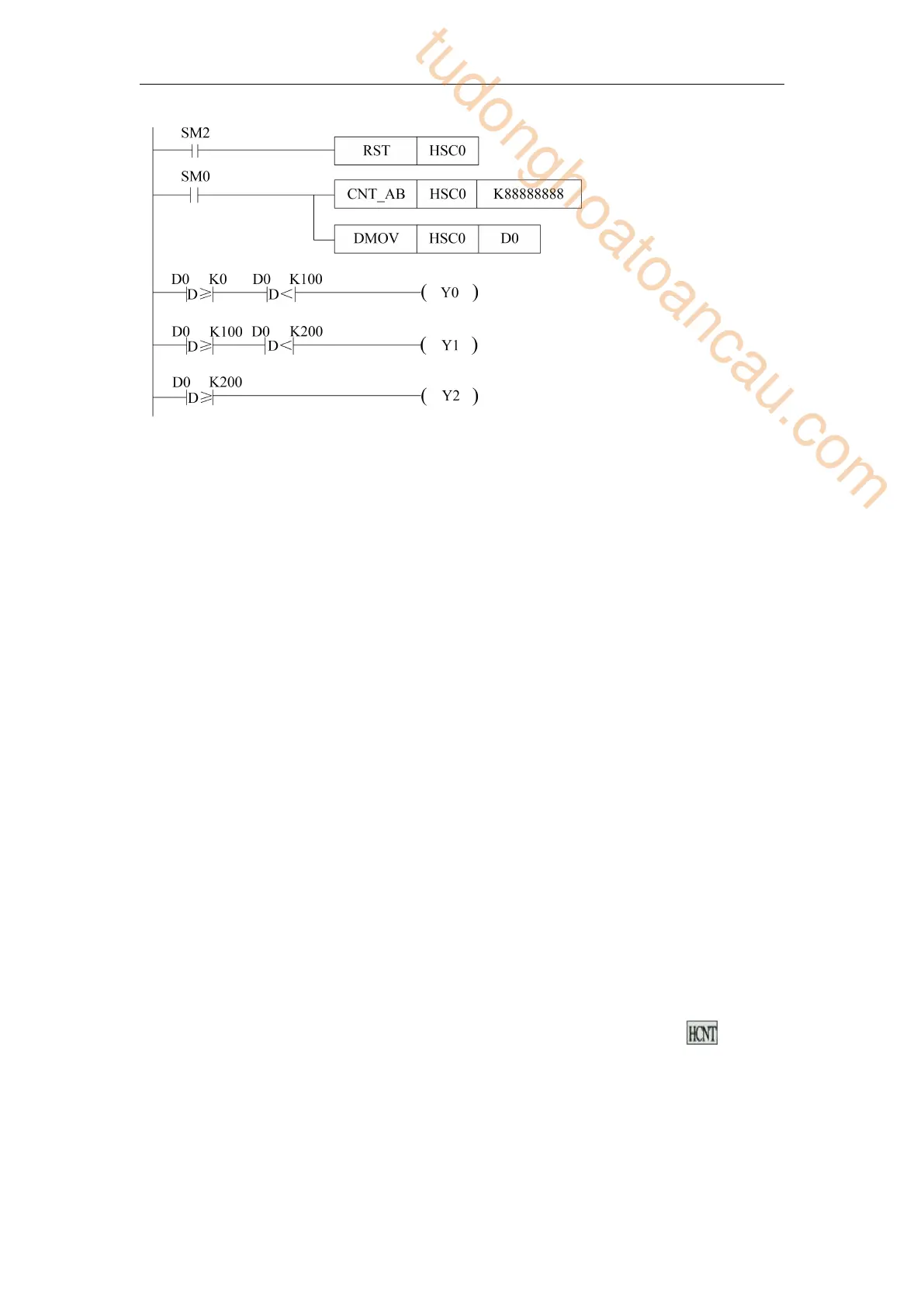
When the rising edge of the original forward pulse coil SM2 comes, that is, at the
beginning of each scanning cycle, HSC0 is reset and the counting value in HSCD0 is
cleared.
When coil SM0 is on, HSC0 begins to count X0 and X1 ports in AB phase mode. The
setting value of counting is K888888. At the same time, the counting value in HSCD0
(double words) is written into D0 (double words) in real time.
When the counting value in D0 (double words) is greater than K0 and less than K100, the
output coil Y0 is ON; when the counting value in D0 (double words) is greater than or
equal to K100 and less than K200, the output coil Y1 is ON; and when the counting value
in D0 (double words) is greater than or equal to K200, the output coil Y2 is ON.
Since the high-speed counter is a double words counter, it is necessary to use the double
words comparison instruction DLD ≥ and DLD < for comparison.
5-9 HSC interruption
5-9-1 Function overview and panel configuration
For XD/XL series PLC, some high-speed counters (referring to the high-speed counting input
port allocation table of chapter 5-5 of each type of PLC) have a set value of32 bits in 1-100
sections. When the difference of high-speed counting equals to the set value of corresponding
100 sections, the interruption will occur according to the corresponding interruption mark.
If the set value of N segment is set, there must be interrupt mark and interrupt program
corresponding to N segment. The interruption marks corresponding to each high-speed
counter are shown in chapter 5-9-4.
When using high-speed counting interrupt function, instructions can be written directly (see
chapters 5-9-2 and 5-9-3), or can be configured by software panel. Please click in the
XDPPro software, it will show below window.
Since the high-speed count value is 32-bit, the
instructions here are all 32-bit
instructions.Such as DMOV,DLD<,
DLD≥
tudonghoatoancau.com
 Loading...