48
counting value decreases to the minimum value K-2,147,483,648 will become
K2,147,483,647, the ON/OFF state of the counter will also change with the change of the
count value.
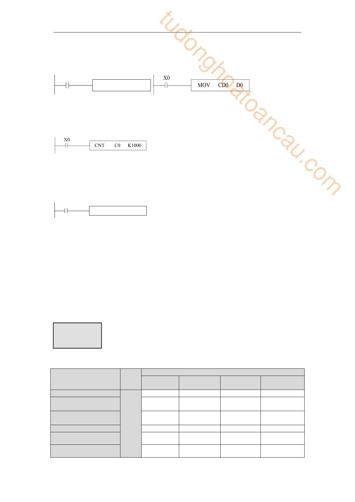
The above two instructions are equivalent. In the left instruction, C0 is processed as a register,
while in the right instruction, CD0 is a data register corresponding to the timer C0. CD and C
are one-to-one correspondences.
The highest frequency that this instruction can count is related to the selection of filter
parameters and the scanning period of PLC. A high-speed counter is recommended when the
input frequency exceeds 25Hz. High-number counter must use HSC0-HSC30 and
corresponding hardware wiring.
High-speed counter, when SM0 is on, HSC0 counts the pulse signal of input terminal X0.
High-speed counter is not affected by the response lag time of input filter and cycle scan time.
Therefore, higher frequency input pulses can be processed. Refer to the details in chapter 5.
Note: The range of soft components mentioned above is the valid range of PLC in the X-NET
communication mode. In the MODBUS communication mode, some relays can not read and
write. The specific usable range is shown in chapter 6-2-3.
2-9 Data register (D, HD, SD, HSD)
The data register of XD/XL series PLC is in decimal format. Please see the following table:
Special power-
off holding
tudonghoatoancau.com
 Loading...