5-44
E
POWR
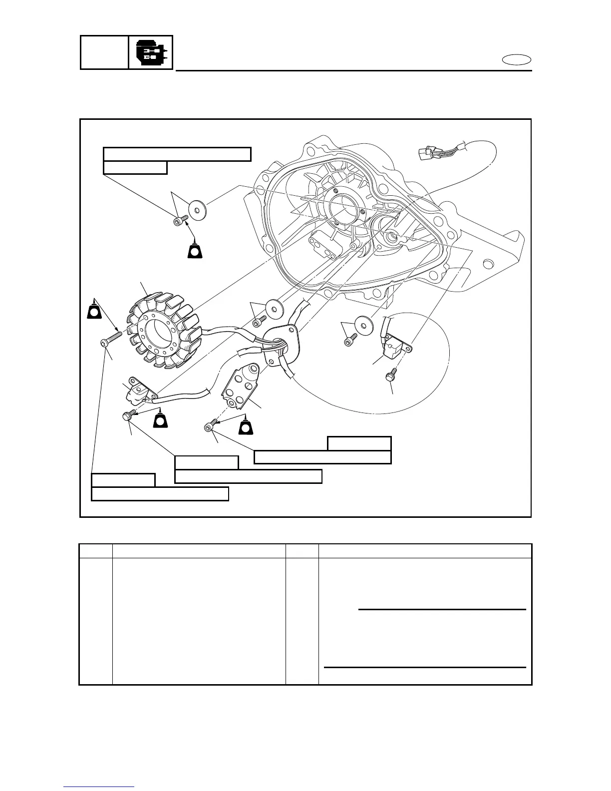
GENERATOR AND STARTER MOTOR
EXPLODED DIAGRAM
REMOVAL AND INSTALLATION CHART
Step Procedure/Part name Q’ty Service points
GENERATOR DISASSEMBLY
Follow the left “Step” for disassembly.
1 Bolt/washer 3/3
2Bolt 4
3 Pickup coil 2
NOTE:
There washers holds the pickup coil lead.
Make sure to not pitch the lead between the
projection and the washer when installing
the bolt.
4Bolt 2
1
7
6
3
2
4
5
LT
242
LT
242
LT
242
LT
242
14 N
•
m (1.4
kgf • m, 10 ft • Ib)
6 × 14 mm
4.9 N
•
m (0.49
kgf • m, 3.5 ft • Ib)
5 × 14 mm
14 N
•
m (1.4
kgf • m, 10 ft • Ib)
6 × 33 mm
4.9 N
•
m (0.49
kgf • m, 3.5 ft • Ib)
5 × 10 mm
1
1
2
3