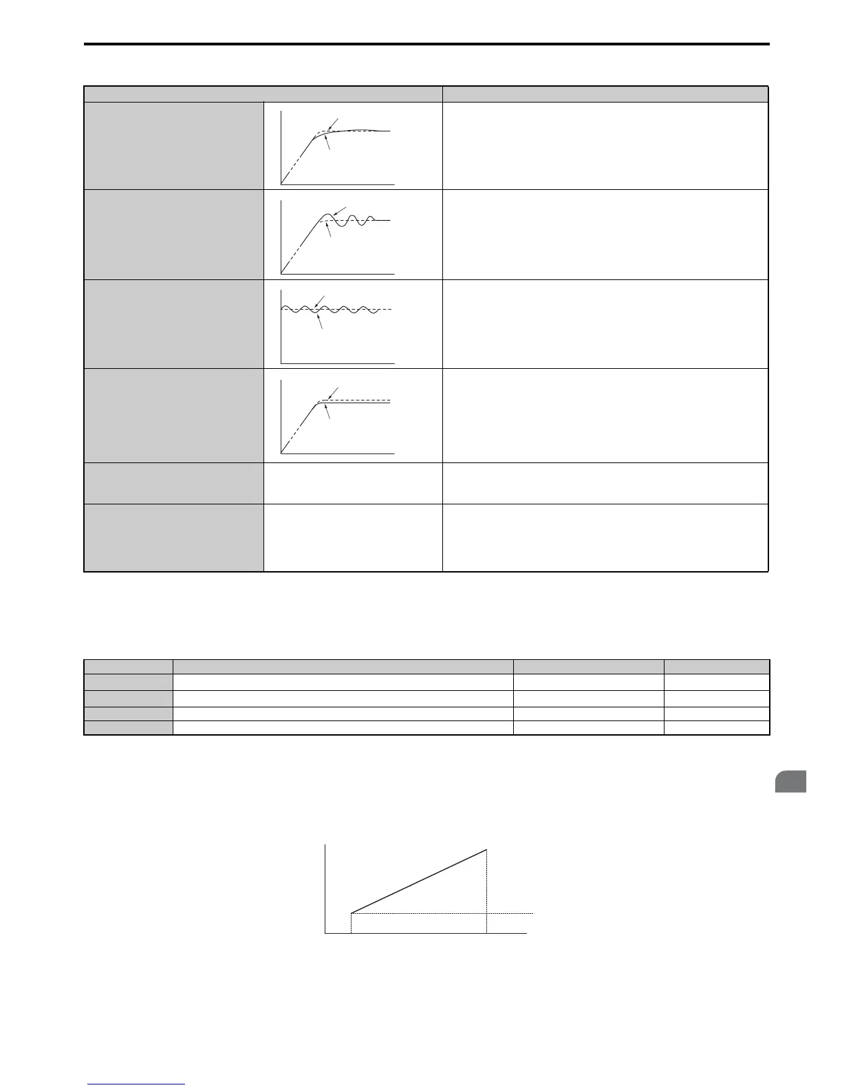
Table 5.14 ASR Setup Problems and Corrective Actions
■ C5-01, C5-03 / C5-02, C5-04: ASR Proportional Gain 1, 2 / ASR Integral Time 1, 2
These parameters can be used to adjust the responsiveness of the ASR.
Note: C5-01 is automatically set when ASR Tuning is performed (T1-01 = 9 or T2-01 = 9).
These parameter settings will function differently depending on the control mode.
V/f Control with PG
Parameters C5-01 and C5-02 determine the ASR characteristics at maximum speed, whereas C5-03 and C5-04 determine
the characteristics at minimum speed.
Figure 5.37
Figure 5.37 ASR Gain and Integral Time in V/fw/PG
Problem Possible Solutions
Slow response to speed changes or speed
deviation lasts for too long
• Increase the ASR gain.
• Decrease the integral time.
Overshoot or undershoot at the end of
acceleration or deceleration
• Decrease the ASR gain.
• Increase the integral time.
Vibration and oscillation occur at constant
speed
• Decrease the ASR gain.
• Increase the integral time.
• Increase the ASR delay time (C5-06).
The motor slip is not fully compensated
when running in V/f Control with PG
• Check the pulse number set to F1-01 and the gear ratio in F1-12 and F1-13.
• Make sure the pulse signal from the encoder is set up properly.
• Check monitor U6-04 and check if the ASR is working at its output limit
(setting of C5-05). If so, increase C5-05.
Integral operation is enabled in V/f
Control with PG (C5-15 = 1) and over/
undershoot occurs when changing speed.
-
• Decrease the ASR gain.
• Increase the integral time.
• If the problem persists, reduce the ASR output limit set in C5-05.
Oscillation at low speed and response is
too slow at high speed (or vice versa)
-
• V/f control: Use C5-01/02 and C5-03/04 to set up different ASR settings at
minimum and maximum speed.
• CLV, AOLV/PM, CLV/PM: Use C5-01, C5-02 and C5-03, C5-04 to define
optimal ASR settings for high and low speed. Use C5-07 to define a
switching frequency.
No. Parameter Name Setting Range Default
C5-01
ASR Proportional Gain 1
0.00 to 300.00 Determined by A1-02
C5-02
ASR Integral Time 1
0.000 to 10.000 s Determined by A1-02
C5-03 ASR Proportional Gain 2 0.00 to 300.00 Determined by A1-02
C5-04 ASR Integral Time 2 0.000 to 10.000 s Determined by A1-02

 Loading...


