5.3 C: Tuning
174 YASKAWA ELECTRIC SIEP C710616 27C YASKAWA AC Drive A1000 Technical Manual
CLV, AOLV/PM, and CLV/PM
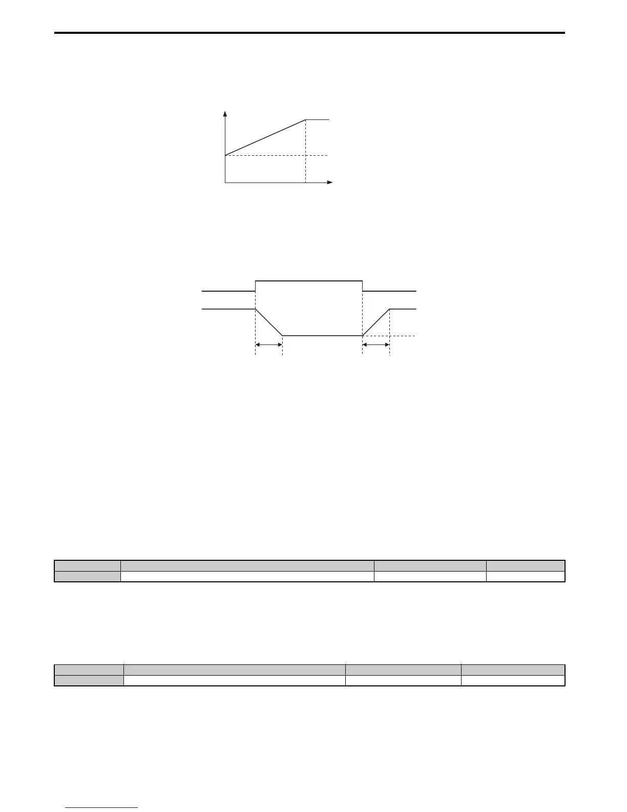
In these control modes, parameters C5-03 and C5-04 define the ASR gain an integral time at zero speed. The settings in
C5-01 and C5-02 are used at speeds above the setting in C5-07. C5-07 is set to 0 as the default so that C5-01 and C5-02
are used over the entire speed range. Also refer to C5-07: ASR Gain Switching Frequency on page 175.
Figure 5. 38
Figure 5.38 Low-speed and High-speed Gain Settings
The gain set in C5-03 can also be activated with a digital input programmed to “ASR gain switch” (H1- = 77). When
the terminal is open, the drive uses the ASR gain level set by the pattern in the figure above. When the terminal closes,
C5-03 is used. The integral time set to C5-02 is used to change linearly between these settings.
The ASR gain switch command from a multi-function input terminal overrides the switching frequency set to C5-07.
Figure 5. 39
Figure 5.39 ASR Proportional Gain Switch
ASR Gain Tuning (C5-01, C5-03)
The higher this setting, the faster is the speed response. Too high of a setting can lead to oscillation. In general, this
setting should be increased with larger loads in order to minimize the speed deviation.
ASR Integral Time Tuning (C5-02, C5-04)
Determines how fast a continuous speed deviation problem is eliminated. Too long of an integral time makes the speed
control less responsive, while a too short of an integral time can cause oscillation.
■
C5-05: ASR Limit
Sets the ASR output limit as a percentage of the maximum output frequency (E1-04). If the motor rated slip is high, the
setting might need to be increased to provide proper motor speed control. Use the ASR output monitor U6-04 to
determine if ASR is working at the limit set in C5-05. If so, make sure the PG pulses (F1-01), PG gear teeth (F1-12, F1-
13), and the PG signal are set correctly before making further changes to C5-05.
■
C5-06: ASR Primary Delay Time Constant
This parameter sets the filter time constant for the time from the speed loop to the torque command output.
Increase this setting gradually in increments of 0.01 for loads with low rigidity, or when oscillation is a problem.
Note: This parameter rarely requires adjustment.
No. Parameter Name Setting Range Default
C5-05 ASR Limit 0.0 to 20.0% 5.0%
No. Parameter Name Setting Range Default
C5-06 ASR Primary Delay Time Constant 0.000 to 0.500 s Determined by A1-02

 Loading...


