Figure 5.60 shows an operation example of Fast Stop.
Figure 5.60
Figure 5.60 Fast Stop Sequence
NOTICE: Rapid deceleration can trigger an overvoltage fault. When faulted, the drive output shuts off, and the motor coasts. To avoid
this uncontrolled motor state and to ensure that the motor stops quickly and safely, set an appropriate Fast Stop time to C1-09.
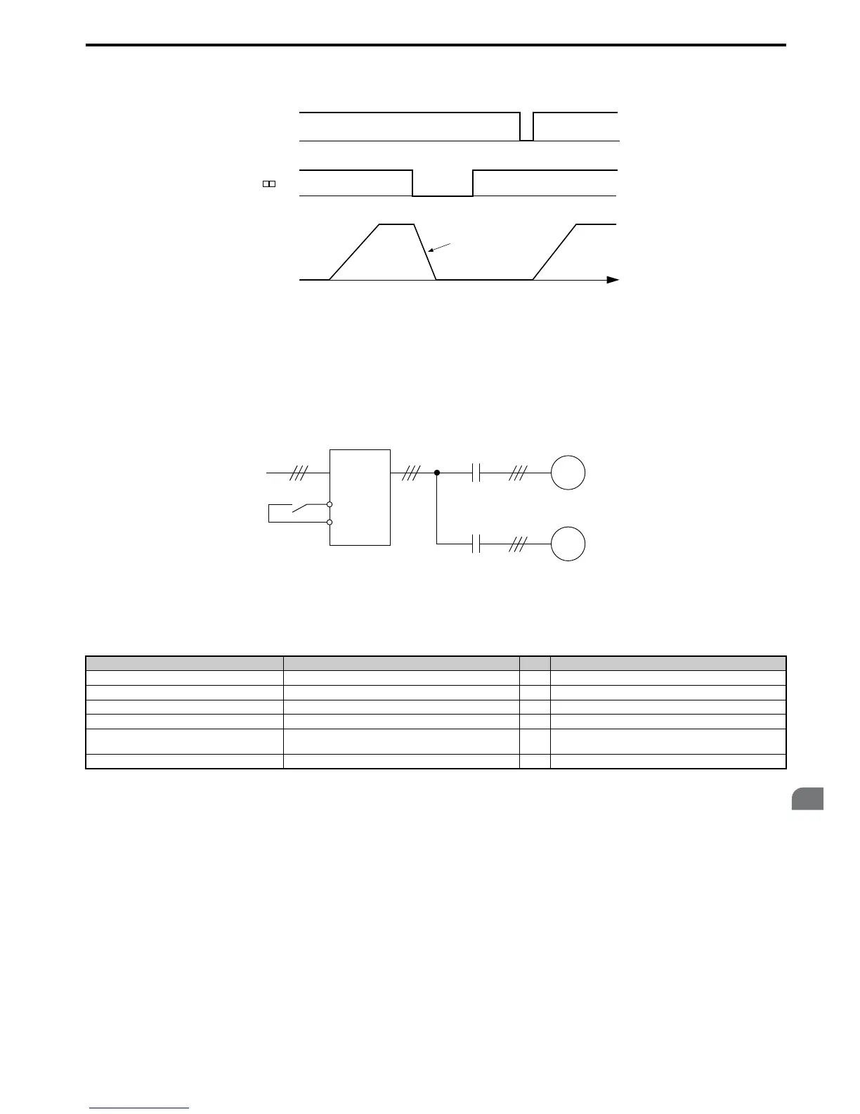
Setting 16: Motor 2 selection
The drive has the capability to control two induction motors independently. A second motor may be selected using a
multi-function digital input as shown in Figure 5.61.
Note: The motor 2 selection function cannot be used when PM motor is used.
Figure 5.61
Figure 5.61 Motor Selection
When switching between motor 1 and motor 2, the parameters used to control those motors also change. Below,
Table 5.3 6 lists the parameters that correspond to each motor.
Table 5.36 Parameters for Switching Between Two Motors
Note: 1. When using 2 motors, the motor overload protection selection (oL1) set to L1-01 applies to both motor 1 and motor 2.
2. It is not possible to switch between motor 1 and motor 2 during run. Doing so will trigger the “rUn” alarm.
3. There is a 500 ms delay when switching between motors equipped with a PG encoder for feedback.
4. The motor 2 selection function cannot be used when PM motor is used.
If a digital output is programmed for “Motor 2 selection” (H1-01, H1-02, or H1-03 = 1C), motor will be selected when
the output is closed.
Setting 18: Timer function input
This setting configures a digital input terminal as the input for the timer function. Use this setting combination with the
timer function output (H2- = 12). Refer to b4: Delay Timers on page 151 for details.
Setting 19: PID disable
When the PID function has been enabled by parameter b5-01, it can be indefinitely disabled by closing a digital input.
When the input is released, the drive resumes PID operation. Also refer to PID Block Diagram on page 154.
No. Setting 16 Open (Motor 1) ⇒ Setting 16 Closed (Motor 2)
C1-: Acceleration/Deceleration Time C1-01 to C1-04 ⇒ C1-05 to C1-08
C3-: Motor Slip Compensation C3-01 to C3-04, C3-15 ⇒ C3-21 to C3-25
C4-: Motor Torque Compensation C4-01 ⇒ C4-07
C5-: Speed Control (ASR) C5-01 to C5-08, C5-12, C5-15, C5-17, C5-18 ⇒ C5-21 to C5-28, C5-32, C5-35, C5-37, C5-38
E1-, E3-: V/f Pattern
E2-, E4-: Motor Parameters
E1-, E2- ⇒ E3- to E4-
F1- (PG Constant) F1-01 to F1-21 ⇒ F1-02 to F1-04, F1-08 to F1-11, F1-14, F1-31 to F1-37

 Loading...


