5.7 H: Terminal Functions
220 YASKAWA ELECTRIC SIEP C710616 27C YASKAWA AC Drive A1000 Technical Manual
Setting 1A: Accel/decel time selection 2
Used to select accel/decel times 1 to 4 in combination with the Accel/decel time selection 1 command. Refer to C1-01 to
C1-08: Accel, Decel Times 1 to 4 on page 165 for details.
Setting 1B: Program lockout
When an input is programmed for Program Lockout, parameters values cannot be changed as long as this input is open (it
is still possible to view and monitor parameter settings).
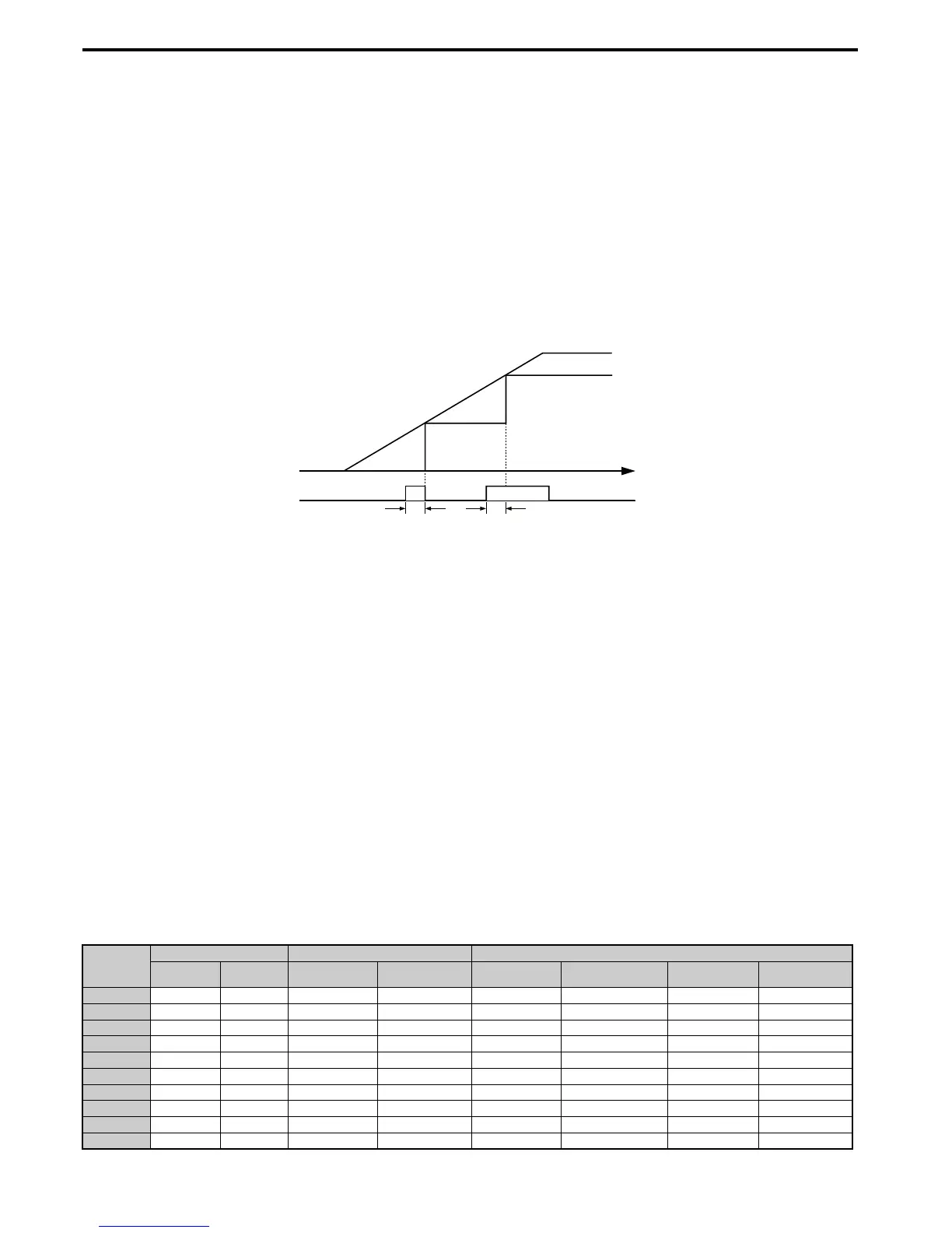
Setting 1E: Reference sample hold
This function allows the user to sample an analog frequency reference signal being input to terminal A1, A2, or A3 and
hold the frequency reference at the sampled level. Once the Analog Frequency Reference Sample/Hold function is held
for at least 100 ms, the drive reads the analog input and changes the frequency reference to the newly sampled speed as
illustrated in Figure 5.62.
When the power is shut off and the sampled analog frequency reference is cleared, the frequency reference is reset to 0.
Figure 5. 62
Figure 5.62 Analog Frequency Reference Sample/Hold
An oPE03 error will occur when one of the following functions is used simultaneously with the Analog frequency
reference sample/hold command.
• Hold accel/decel stop (setting: A)
• Up command, Down command (setting: 10, 11)
• Offset frequency (setting: 44 to 46)
• Up or Down functions (setting: 75, 76)
Setting 20 to 2F: External fault
By using the External fault command, the drive can be stopped when problems occur with external devices.
To use the External fault command, set one of the multi-function digital inputs to any value between 20 to 2F. The digital
operator will display EF where is the number of the terminal to which the external fault signal is assigned.
For example, if an external fault signal is input to terminal S3, “EF3” will be displayed.
Select the value to be set in H1- from a combination of any of the following three conditions:
• Signal input level from peripheral devices (N.O., N.C.)
• External fault detection method
• Operation after external fault detection
The following table shows the relationship between the conditions and the value set to H1-:
Setting
Terminal Status <1> Detection Conditions <2> Stopping Method
N.O. N.C. Always Detected
Detected during
Run only
Ramp to Stop
(fault)
Coast to Stop
(fault)
Fast Stop
(fault)
Alarm Only
(continue running)
20 O O O
21 O O O
22 O O O
23 O O O
24 O O O
25 O O O
26 O O O
27 O O O
28 O O O
29 O O O

 Loading...


