5.7 H: Terminal Functions
232 YASKAWA ELECTRIC SIEP C710616 27C YASKAWA AC Drive A1000 Technical Manual
Setting 2F: Maintenance period
Output closes when the cooling fan, DC bus capacitors, or DC bus pre-charge relay may require maintenance as
determined by the estimated performance life span of those components. Components performance life is displayed as a
percentage on the digital operator screen. Refer to Periodic Maintenance on page 349.
Setting 30: During torque limit
Output closes when the motor is operating at the torque limit specified by the L7- parameters or an analog input.
This setting can only be used in OLV, CLV, AOLV/PM and CLV/PM control modes. Refer to L7-01 to L7-04: Torque
Limits on page 268 for details.
Setting 31: During speed limit
Output closes when the speed limit has been reached. This function can be used in CLV and CLV/PM control modes.
Setting 32: During speed limit in Torque Control
The motor torque and load torque are not in balance, causing the motor to accelerate. An output terminal set to 32 closes
when the motor reaches the speed limit. Refer to d5: Torque Control on page 188 and Indicating Operation at the Speed
Limit on page 190 for details.
Setting 33: Zero Servo complete
Output closes when Zero Servo is enabled and the load is locked into position within the allowable deviation (b9-02). For
how Zero Servo operates, see b9: Zero Servo on page 164.
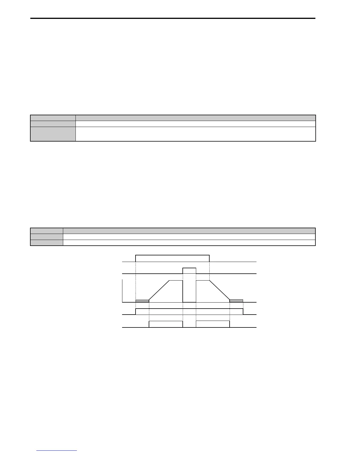
Setting 37: During frequency output
Output closes when the drive is outputting a frequency.
Figure 5. 76
Figure 5.76 During Frequency Output Time Chart
Setting 38: Drive enable
A digital output set for “Drive enable” will reflect the status of a digital input configured as a “Drive enable” input (H1-
= 6A). If that digital input closes, then the digital output set for “Drive enable” will also close.
Setting 39: Watt hour pulse output
Outputs a pulse to indicate the watt hours. Refer to H2-06: Watt Hour Output Unit Selection on page 234 for details.
Status Description
Open The conditions described below are not present.
Closed
1. The frequency reference has reached the upper limit set in d2-01.
2. The frequency reference has fallen to the lower limit set in d2-02 or d2-03.
3. Parameter b1-05 is set to 1, 2, or 3, and the frequency reference has fallen below the minimum output frequency (E1-09).
Status Description
Open Drive is stopped or one of the following functions is being performed: baseblock, DC Injection Braking, Short Circuit Braking.
Closed Drive is outputting frequency.

 Loading...


