Setting Examples
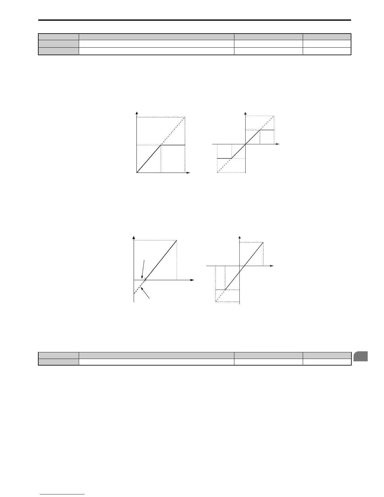
• Gain H3-03 = 200%, bias H3-04 = 0, terminal A1 as frequency reference input (H3-02 = 0):
An input 10 Vdc will be equivalent to a 200% frequency reference and 5 Vdc will be equivalent to a 100% frequency
reference. Since the drive output is limited by the maximum frequency parameter (E1-04), the frequency reference will
be equal to E1-04 above 5 Vdc.
Figure 5.78
Figure 5.78 Frequency Reference Setting by Analog Input with Increased Gain
• Gain H3-03 = 100%, bias H3-04 = -25%, terminal A1 as frequency reference input:
An input of 0 Vdc will be equivalent to a -25% frequency reference.
When parameter H3-01 = 0, the frequency reference is 0% between 0 and 2 Vdc input.
When parameter H3-01 = 1, the motor will rotate in reverse between -10 and 2 Vdc input.
Figure 5.79
Figure 5.79 Frequency Reference Setting by Analog Input with Negative Bias
■ H3-05: Terminal A3 Signal Level Selection
Selects the input signal level for analog input A3. Refer to Multi-Function Analog Input Terminal Settings on page 237
for a list of functions and descriptions.
Setting 0: 0 to 10 Vdc
The input level is 0 to 10 Vdc. See the explanation provided for H3-01. Refer to Setting 0: 0 to 10 Vdc on page 234.
Setting 1: –10 V to 10 Vdc
The input level is –10 to 10 Vdc. See the explanation provided for H3-01. Refer to Setting 1: –10 to 10 Vdc on page 234.
■
H3-06: Terminal A3 Function Selection
Determines the function assigned to analog input terminal A3. Refer to Multi-Function Analog Input Terminal Settings
on page 237 for a list of functions and descriptions.
No. Name Setting Range Default
H3-03
Terminal A1 Gain Setting
-999.9 to 999.9% 100.0%
H3-04
Terminal A1 Bias Setting
-999.9 to 999.9% 0.0%
No. Name Setting Range Default
H3-05 Terminal A3 Signal Level Selection 0, 1 0
100%
-100%
5 V
10 V
-5 V-10 V
E1-04
E1-04
H3-01 = 0 H3-01 = 1
0 V
10 V5 V
0 V
Gain = 200 %
Gain = 200 %
100 %
Frequecny
reference
Bias = 0 %
E1-04
Gain = -200 %

 Loading...


