5.7 H: Terminal Functions
236 YASKAWA ELECTRIC SIEP C710616 27C YASKAWA AC Drive A1000 Technical Manual
When analog input A3 is used as PTC input set H3-06 = E and make sure switch S4 on the terminal board is set for PTC
input. Also refer to Terminal A3 Analog/PTC Input Selection on page 79.
■
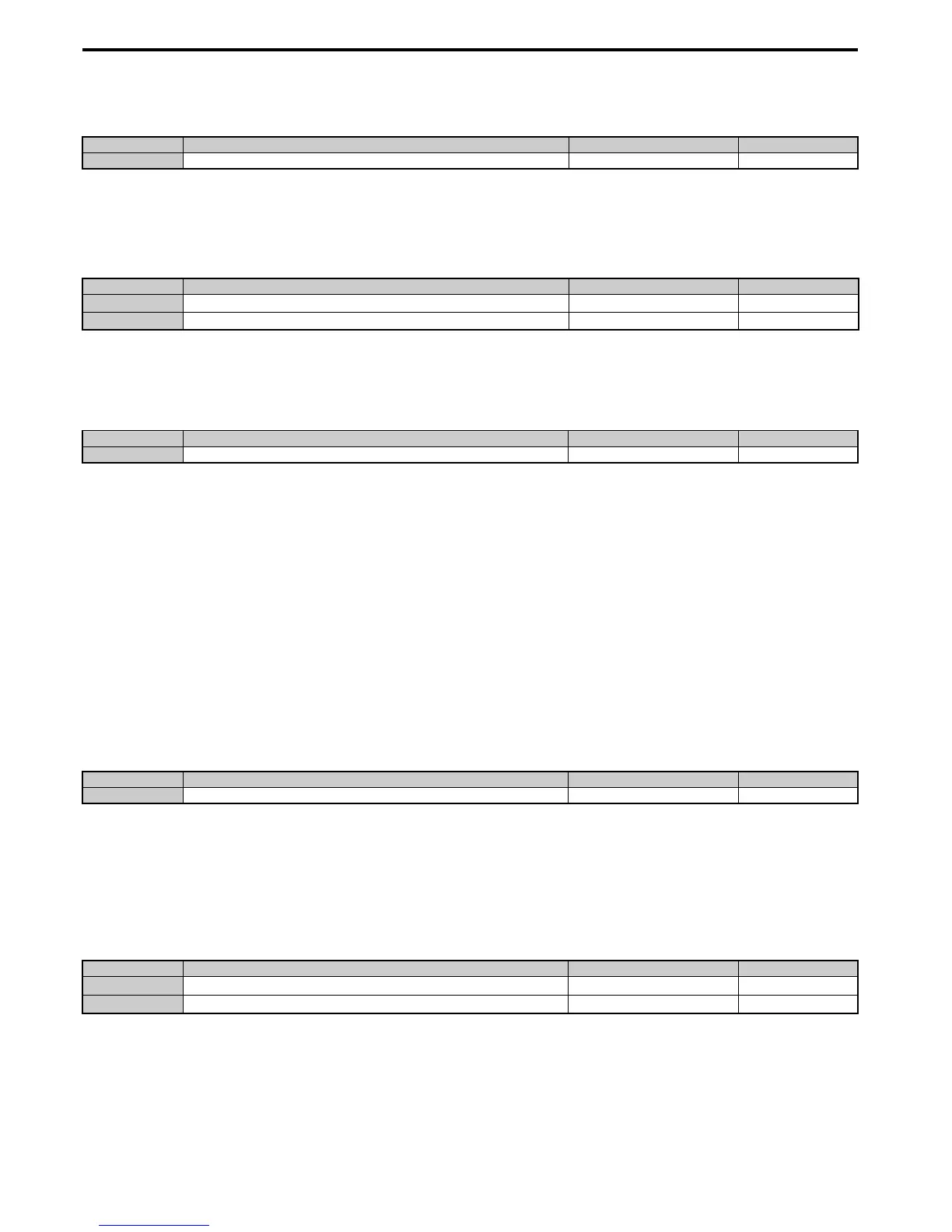
H3-07, H3-08: Terminal A3 Gain and Bias Setting
Parameter H3-07 sets the level of the selected input value that is equal to 10 Vdc input at terminal A3 (gain).
Parameter H3-08 sets the level of the selected input value that is equal to 0 V input at terminal A3 (bias).
■
H3-09: Terminal A2 Signal Level Selection
Selects the input signal level for analog input A2. Be sure to also set DIP switch S1 on the terminal board accordingly for
a voltage input or current input.
Setting 0: 0 to 10 Vdc
The input level is 0 to 10 Vdc. Refer to Setting 0: 0 to 10 Vdc on page 234
Setting 1: –10 to 10 Vdc
The input level is –10 to 10 Vdc. Refer to Setting 1: –10 to 10 Vdc on page 234.
Setting 2: 4 to 20 mA Current Input
The input level is 4 to 20 mA. Negative input values by negative bias or gain settings will be limited to 0%.
Setting 3: 0 to 20 mA Current Input
The input level is 0 to 20 mA. Negative input values by negative bias or gain settings will be limited to 0%.
■
H3-10: Terminal A2 Function Selection
Determines the function assigned to analog input terminal A2. Refer to Multi-Function Analog Input Terminal Settings
on page 237 for a list of functions and descriptions.
■
H3-11, H3-12: Terminal A2 Gain and Bias Setting
Parameter H3-11 sets the level of the input value selected that is equal to 10 Vdc input or 20 mA input to terminal A2.
Parameter H3-12 sets the level of the input value selected that is equal to 0 V, 4 mA or 0 mA input at terminal A2.
Both can be used to adjust the characteristics of the analog input signal to terminal A2. The setting works in the same
way as parameters H3-03 and H3-04 for analog input A1.
■
H3-13: Analog Input Filter Time Constant
Parameter H3-13 sets the time constant for a first order filter that will be applied to the analog inputs.
An analog input filter can be used to prevent erratic drive control when a “noisy” analog reference is used. The drive
operation becomes more stable the longer the time programmed, but it becomes less responsive to rapidly changing
analog signals.
No. Name Setting Range Default
H3-06 Terminal A3 Function Selection 0 to 31 2
No. Name Setting Range Default
H3-07
Terminal A3 Gain Setting
-999.9 to 999.9% 100.0%
H3-08
Terminal A3 Bias Setting
-999.9 to 999.9% 0.0%
No. Name Setting Range Default
H3-09 Terminal A2 Signal Level Selection 0 to 3 2
No. Name Setting Range Default
H3-10 Terminal A2 Function Selection 0 to 31 0
No. Name Setting Range Default
H3-11
Terminal A2 Gain Setting
-999.9 to 999.9% 100.0%
H3-12
Terminal A2 Bias Setting
-999.9 to 999.9% 0.0%

 Loading...


