■ H3-14: Analog Input Terminal Enable Selection
When one of the multi-function digital input parameters is set for “Analog input enable” (H1- = C), the value set to
H3-14 determines which analog input terminals are enabled and which terminals are disabled when the input is closed.
All analog input terminals will be enabled all of the time if H1- is not set to C.
Setting 1: A1 only enabled
Setting 2: A2 only enabled
Setting 3: A1 and A2 only enabled
Setting 4: A3 only enabled
Setting 5: A1 and A3 only enabled
Setting 6: A2 and A3 only enabled
Setting 7: All analog input terminals enabled
■ Multi-Function Analog Input Terminal Settings
See Table 5. 39 for information on how H3-02, H3-10, and H3-06 determine functions for terminals A1, A2, and A3.
Note: The scaling of all input functions depends on the gain and bias settings for the analog inputs. Set these to appropriate values
when selecting and adjusting analog input functions.
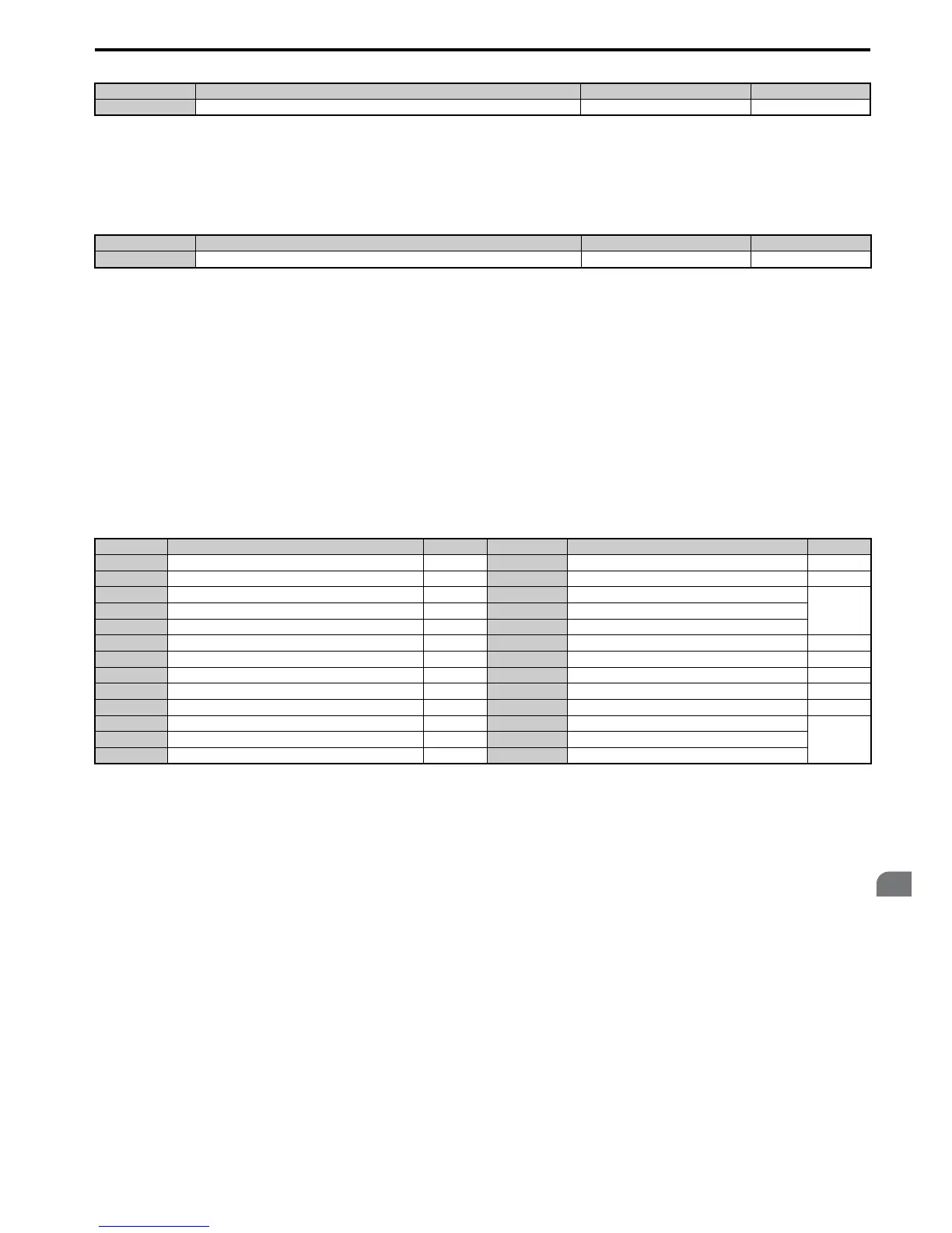
Table 5.39 Multi-Function Analog Input Terminal Settings
Setting 0: Frequency bias
The input value of an analog input set to this function will be added to the analog frequency reference value. When the
frequency reference is supplied by a different source other than the analog inputs, this function will have no effect. Use
this setting also when only one of the analog inputs is used to supply the frequency reference.
By default, analog inputs A1 and A2 are set for this function. Using A1 and A2 at the same time increases the frequency
reference by the total of all inputs.
Example: If the analog frequency reference from analog input terminal A1 is 50% and a bias of 20% is applied by analog
input terminal A2, the resulting frequency reference will be 70% of the maximum output frequency.
Setting 1: Frequency gain
The input value of an analog input set to this function will be multiplied with the analog frequency reference value.
Example: If the analog frequency reference from analog input terminal A1 is 80% and a gain of 50% is applied from
analog input terminal A2, the resulting frequency reference will be 40% of the maximum output frequency.
Setting 2: Auxiliary reference 1
Sets the auxiliary frequency reference 1 when multi-step speed operation is selected. Refer to Multi-Step Speed
Selection on page 180 for details.
No. Name Setting Range Default
H3-13 Analog Input Filter Time Constant 0.00 to 2.00 s 0.03 s
No. Name Setting Range Default
H3-14 Analog Input Terminal Enable Selection 1 to 7 7
Setting Function Page Setting Function Page
0 Frequency bias 237 E Motor temperature (PTC input) 239
1 Frequency gain 237 F Through mode 239
2 Auxiliary frequency reference 1 237 10 Forward torque limit
239
3 Auxiliary frequency reference 2 238 11 Reverse Torque Limit
4 Output voltage bias 238 12 Regenerative torque limit
5 Accel/decel time gain 238 13 Torque limit using torque reference/speed limit 239
6 DC Injection Braking current 238 14 Torque compensation 239
7 Torque detection level 238 15 General torque limit 239
8 Stall Prevention level during run 238 16 Differential PID feedback 239
9 Output frequency lower limit level 239 1F Through mode 239
B PID feedback 239 30 DriveWorksEZ analog input 1
239
C PID setpoint 239 31 DriveWorksEZ analog input 2
D Frequency bias 239 32 DriveWorksEZ analog input 3

 Loading...


