5.8 L: Protection Functions
YASKAWA ELECTRIC SIEP C710616 27C YASKAWA AC Drive A1000 Technical Manual 247
Figure 5.87
Figure 5.87 Motor Protection Operation Time
■ Motor Protection Using a Positive Temperature Coefficient (PTC)
A motor PTC can be connected to an analog input of the drive. This input is used by the drive for motor overheat
protection.
When the motor overheat alarm level is reached, an oH3 alarm will be triggered and the drive will continue operation as
selected in L1-03. When the overheat fault level is reached, an oH4 fault will be triggered, a fault signal will be output,
and the drive will stop the motor using the stop method determined in L1-04.
Connect the PTC between terminals AC and A3 and set jumper S4 on the terminal board to “PTC” like shown in
Figure 5.88. Set parameter H3-05 to 0 and parameter H3-06 to E.
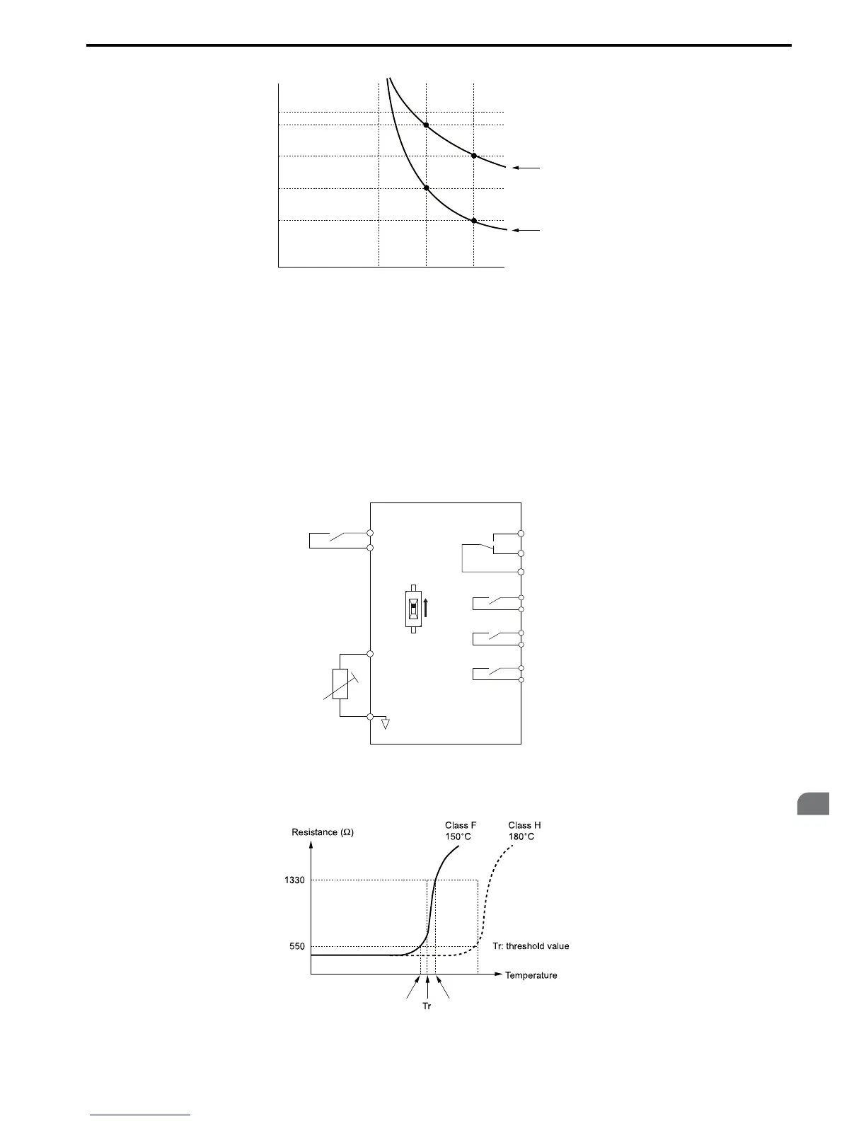
Figure 5.88
Figure 5.88 Connection of a Motor PTC
The PTC must have the following characteristics for one motor phase. The drives motor overload detection expects 3 of
these PTCs to be connected in series.
Figure 5.89
Figure 5.89 Motor PTC Characteristics

 Loading...


