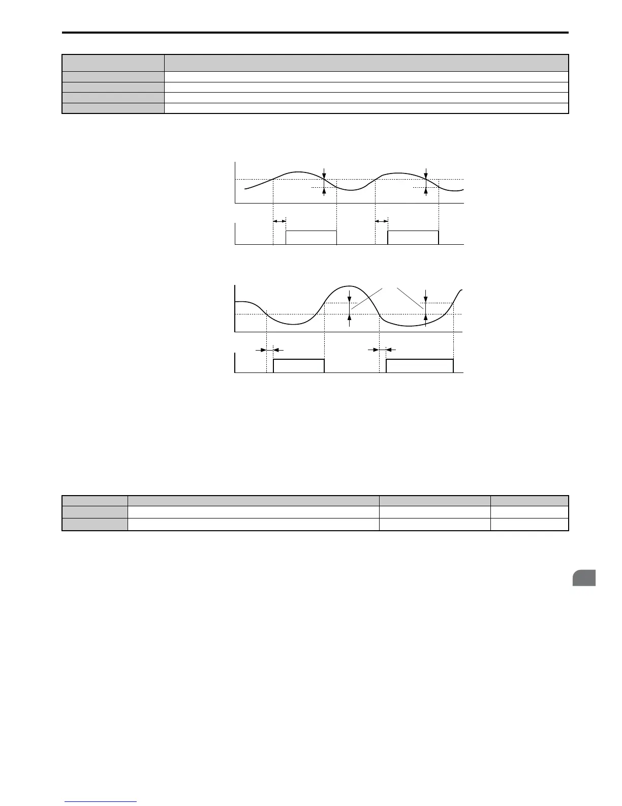
Figure 5.101 and Figure 5.102 show the function of overtorque and undertorque detection.
Figure 5.1 01
Figure 5.101 Overtorque Detection Operation
Figure 5.1 02
Figure 5.102 Undertorque Detection Operation
Note: 1. The torque detection function uses a hysteresis of 10% of the drive rated output current and motor rated torque.
2. In V/f, V/f w/PG and OLV/PM, the level is set as a percentage of the drive rated output current. In OLV, CLV, AOLV/PM and CLV/
PM, it is set as a percentage of the motor rated torque.
■ L6-01, L6-04: Torque Detection Selection 1, 2
The torque detection function is triggered when the current or torque exceeds the levels set in L6-02 and L6-05 for longer
than the time set in L6-03 and L6-06. L6-01 and L6-04 select the conditions for detection and the operation that follows.
Setting 0: Disabled
Setting 1: oL3, oL4 at speed agree (alarm)
Overtorque detection is active only when the output speed is equal to the frequency reference, i.e., no detection during
acceleration and deceleration. The operation continues after detection and an oL3/oL4 alarm is triggered.
Setting 2: oL3, oL4 at run (alarm)
Overtorque detection works as long as the Run command is active. The operation continues after detection and an oL3 or
oL4 alarm is triggered.
Setting 3: oL3, oL4 at speed agree (fault)
Overtorque detection is active only when the output speed is equal to the frequency reference, i.e., no detection during
acceleration and deceleration. The operation is stopped and an oL3 or oL4 fault is triggered.
Setting 4: oL3, oL4 at run - (fault)
Overtorque detection works as long as a Run command is active. Operation stops and an oL3 or oL4 fault is triggered.
H2-01, H2-02, H2-03
Setting
Description
B Torque detection 1, N.O. (output closes when overload or underload is detected)
17 Torque detection 1, N.C. (output opens when overload or underload is detected
18 Torque detection 2, N.O. (output close when overload or underload is detected)
19 Torque detection 2, N.C. (output opens when overload or underload is detected)
No. Name Setting Range Default
L6-01
Torque Detection Selection 1
0 to 8 0
L6-04
Torque Detection Selection 2
0 to 8 0

 Loading...


