B.3 Parameter Table
402 YASKAWA ELECTRIC SIEP C710616 27C YASKAWA AC Drive A1000 Technical Manual
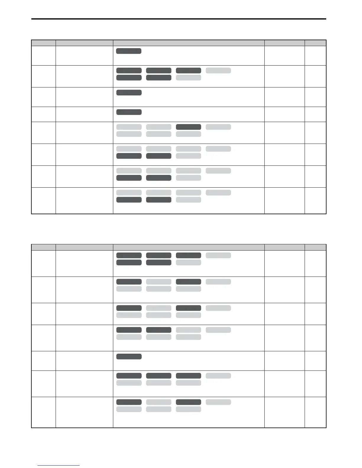
■ b2: DC Injection Braking and Short Circuit Braking
■ b3: Speed Search
No.(Addr.) Name Description Setting Page
b2-01
(189H)
<7> A coasting motor may require a braking resistor circuit to bring the motor to a stop in the required time.
<10> Default setting is determined by the control mode (A1-02).
DC Injection Braking Start
Frequency
Sets the frequency at which DC Injection Braking starts when “Ramp to stop” (b1-03 = 0) is
selected.
Default:
<10>
Min: 0.0 Hz
Max: 10.0 Hz
144
b2-02
(18AH)
DC Injection Braking Current
Sets the DC Injection Braking current as a percentage of the drive rated current.
Default: 50%
Min: 0%
Max: 100%
145
b2-03
(18BH)
DC Injection Braking Time at Start
Sets the time of DC Injection Braking (Zero Speed Control when in CLV and CLV/PM) time at
start. Disabled when set to 0.00 s.
Default: 0.00 s
Min: 0.00 s
Max: 10.00 s
145
b2-04
(18CH)
DC Injection Braking Time at Stop
Sets the time of DC Injection Braking (Zero Speed Control when in CLV and CLV/PM) at stop.
Default:
<10>
Min: 0.00 s
Max: 10.00 s
145
b2-08
(190H)
Magnetic Flux Compensation
Va lu e
Sets the magnetic flux compensation as a percentage of the no-load current value (E2-03).
Default: 0%
Min: 0%
Max: 1000%
145
b2-12
(1BAH)
Short Circuit Brake Time at Start
Sets the time for Short Circuit Braking operation at start.
<7>
Default: 0.00 s
Min: 0.00 s
Max: 25.50 s
146
b2-13
(1BBH)
Short Circuit Brake Time at Stop
Sets the Short Circuit Braking operation time at stop.
<7>
Default: 0.50 s
Min: 0.00 s
Max: 25.50 s
146
b2-18
(177H)
Short Circuit Braking Current
Determines the current level for Short Circuit Braking. Set as a percentage of the motor rated
current.
Default: 100.0%
Min: 0.0%
Max: 200.0%
146
No.(Addr.) Name Description Setting Page
b3-01
(191H)
Speed Search Selection at Start
0: Disabled
1: Enabled
Default:
<10>
Min: 0
Max: 1
149
b3-02
(192H)
Speed Search Deactivation Current
Sets the current level at which the speed is assumed to be detected and Speed Search is ended.
Set as a percentage of the drive rated current.
Default:
<10>
Min: 0%
Max: 200%
149
b3-03
(193H)
Speed Search Deceleration Time
Sets output frequency reduction time during Speed Search.
Default: 2.0 s
Min: 0.1 s
Max: 10.0 s
149
b3-04
(194H)
V/f Gain during Speed Search
Determines how much to lower the V/f ratio during Speed Search.
Output voltage during Speed Search equals the V/f setting multiplied by b3-04.
Default:
<9>
Min: 10%
Max: 100%
150
b3-05
(195H)
Speed Search Delay Time
When using an external contactor on the output side, b3-05 delays executing Speed Search after
a momentary power loss to allow time for the contactor to close.
Default: 0.2 s
Min: 0.0 s
Max: 100.0 s
150
b3-06
(196H)
Output Current 1 during Speed
Search
Sets the current injected to the motor at the beginning of Speed Estimation Speed Search. Set as
a coefficient for the motor rated current.
Default:
<9>
Min: 0.0
Max: 2.0
150
b3-10
(19AH)
Speed Search Detection
Compensation Gain
Sets the gain which is applied to the speed detected by Speed Estimation Speed Search before
the motor is reaccelerated. Increase this setting if ov occurs when performing Speed Search
after a relatively long period of baseblock.
Default: 1.05
Min: 1.00
Max: 1.20
150
All Modes

 Loading...


