■ b4: Timer Function
■ b5: PID Control
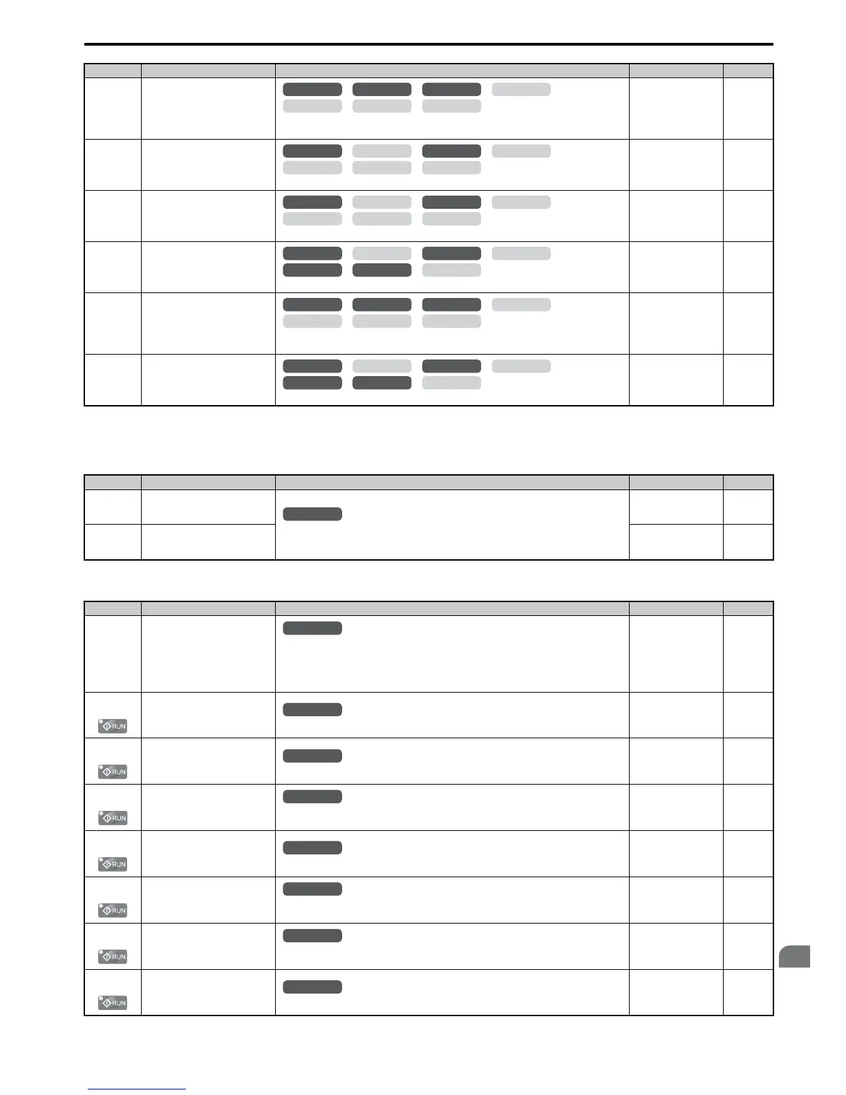
b3-14
(19EH)
Bi-Directional Speed Search
Selection
0: Disabled (uses the direction of the frequency reference)
1: Enabled (drive detects which way the motor is rotating)
Default:
<10>
Min: 0
Max: 1
150
b3-17
(1F0H)
Speed Search Restart Current
Level
Sets the Speed Search restart current level as a percentage of the drive rated current.
Default: 150%
Min: 0%
Max: 200%
150
b3-18
(1F1H)
Speed Search Restart Detection
Time
Sets the time to detect Speed Search restart.
Default: 0.10 s
Min: 0.00 s
Max: 1.00 s
151
b3-19
(1F2H)
Number of Speed Search Restarts
Sets the number of times the drive can attempt to restart when performing Speed Search.
Default: 3
Min: 0
Max: 10
151
b3-24
(1C0H)
Speed Search Method Selection
0: Current Detection
1: Speed Estimation
Default: 0
Min: 0
Max: 1
151
b3-25
(1C8H)
Speed Search Wait Time
Sets the time the must wait between each Speed Search restart attempt.
Default: 0.5 s
Min: 0.0 s
Max: 30.0 s
151
<9> Default setting value is dependent on the drive model (o2-04) and the Drive Duty (C6-01).
<10> Default setting is determined by the control mode (A1-02).
No.(Addr.) Name Description Setting Page
b4-01
(1A3H)
Timer Function On-Delay Time
Used to set the on-delay and off-delay times for a digital timer output (H2-=12). The output
is triggered by a digital input programmed to H1-=18)
Default: 0.0 s
Min: 0.0 s
Max: 3000.0 s
151
b4-02
(1A4H)
Timer Function Off-Delay Time
Default: 0.0 s
Min: 0.0 s
Max: 3000.0 s
151
No.(Addr.) Name Description Setting Page
b5-01
(1A5H)
PID Function Setting
0: Disabled
1: Enabled (PID output becomes output frequency reference, deviation D controlled)
2: Enabled (PID output becomes output frequency reference, feedback D controlled)
3: Enabled (PID output added to frequency reference, deviation D controlled)
4: Enabled (PID output added to frequency reference, feedback D controlled)
Default: 0
Min: 0
Max: 4
155
b5-02
(1A6H)
Proportional Gain Setting (P)
Sets the proportional gain of the PID controller.
Default: 1.00
Min: 0.00
Max: 25.00
155
b5-03
(1A7H)
Integral Time Setting (I)
Sets the integral time for the PID controller.
Default: 1.0 s
Min: 0.0 s
Max: 360.0 s
155
b5-04
(1A8H)
Integral Limit Setting
Sets the maximum output possible from the integrator as a percentage of the maximum output
frequency.
Default: 100.0%
Min: 0.0%
Max: 100.0%
155
b5-05
(1A9H)
Derivative Time (D)
Sets D control derivative time.
Default: 0.00 s
Min: 0.00 s
Max: 10.00 s
155
b5-06
(1AAH)
PID Output Limit
Sets the maximum output possible from the entire PID controller as a percentage of the
maximum output frequency.
Default: 100.0%
Min: 0.0%
Max: 100.0%
155
b5-07
(1ABH)
PID Offset Adjustment
Applies an offset to the PID controller output. Set as a percentage of the maximum output
frequency.
Default: 0.0%
Min: -100.0%
Max: 100.0%
156
b5-08
(1ACH)
PID Primary Delay Time Constant
Sets a low pass filter time constant on the output of the PID controller.
Default: 0.00 s
Min: 0.00 s
Max: 10.00 s
156
No.(Addr.) Name Description Setting Page

 Loading...


