B.3 Parameter Table
404 YASKAWA ELECTRIC SIEP C710616 27C YASKAWA AC Drive A1000 Technical Manual
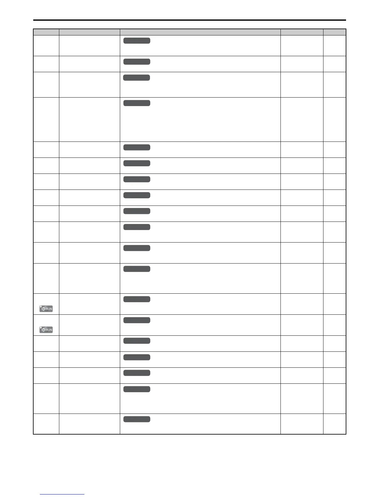
b5-09
(1ADH)
PID Output Level Selection
0: Normal output (direct acting)
1: Reverse output (reverse acting)
Default: 0
Min: 0
Max: 1
156
b5-10
(1AEH)
PID Output Gain Setting
Sets the gain applied to the PID output.
Default: 1.00
Min: 0.00
Max: 25.00
156
b5-11
(1AFH)
PID Output Reverse Selection
0: Negative PID output triggers zero limit.
1: Rotation direction reverses with negative PID output.
When using setting 1, make sure reverse operation is permitted by parameter b1-04.
Default: 0
Min: 0
Max: 1
156
b5-12
(1B0H)
PID Feedback Loss Detection
Selection
0: No fault. Digital output only.
1: Fault detection. Alarm output, drive continues operation.
2: Fault detection. Fault output, drive output is shut off.
3: No fault. Digital output only. No fault detection when PID control is disabled.
4: Fault detection. Alarm is triggered and drive continues to run. Fault detection even when PID
is disabled.
5: Fault detection. Drive output shuts off. No fault detection when PID control is disabled.
Default: 0
Min: 0
Max: 5
157
b5-13
(1B1H)
PID Feedback Loss Detection
Level
Sets the PID feedback loss detection level as a percentage of the maximum output frequency.
Default: 0%
Min: 0%
Max: 100%
158
b5-14
(1B2H)
PID Feedback Loss Detection
Time
Sets a delay time for PID feedback loss.
Default: 1.0 s
Min: 0.0 s
Max: 25.5 s
158
b5-15
(1B3H)
PID Sleep Function Start Level
Sets the frequency level that triggers the sleep function.
Default: 0.0 Hz
Min: 0.0 Hz
Max: 400.0 Hz
158
b5-16
(1B4H)
PID Sleep Delay Time
Sets a delay time before the sleep function is triggered.
Default: 0.0 s
Min: 0.0 s
Max: 25.5 s
159
b5-17
(1B5H)
PID Accel/Decel Time
Sets the acceleration and deceleration time to PID setpoint.
Default: 0.0 s
Min: 0.0 s
Max: 6000.0 s
159
b5-18
(1DCH)
PID Setpoint Selection
0: Disabled
1: Enabled
Default: 0
Min: 0
Max: 1
159
b5-19
(1DDH)
PID Setpoint Value
Sets the PID target value when b5-18 = 1. Set as
a percentage of t
he maximum output
frequency.
Default: 0.00%
Min: 0.00%
Max: 100.00%
159
b5-20
(1E2H)
PID Setpoint Scaling
0: 0.01Hz units
1: 0.01% units (100% = max output frequency)
2: r/min (number of motor poles must entered)
3: User-set (set scaling to b5-38 and b5-39)
Default: 1
Min: 0
Max: 3
159
b5-34
(19FH)
PID Output Lower Limit
Sets the minimum output possible from the PID controller as a percentage of the maximum
output frequency.
Default: 0.00%
Min: -100.0%
Max: 100.0%
160
b5-35
(1A0H)
PID Input Limit
Limits the PID control input (deviation signal) as a percentage of the maximum output
frequency. Acts as a bipolar limit.
Default: 1000.0%
Min: 0%
Max: 1000.0%
160
b5-36
(1A1H)
PID Feedback High Detection
Level
Sets the PID feedback high detection level as a percentage of the maximum output frequency.
Default: 100%
Min: 0%
Max: 100%
158
b5-37
(1A2H)
PID Feedback High Detection
Time
Sets the PID feedback high level detection delay time.
Default: 1.0 s
Min: 0.0 s
Max: 25.5 s
158
b5-38
(1FEH)
PID Setpoint User Display
Sets the display value of U5-01 and U5-04 when the maximum frequency is output.
Default:
<5>
Min: 1
Max: 60000
160
b5-39
(1FFH)
PID Setpoint Display Digits
0: No decimal places
1: One decimal places
2: Two decimal places
3: Three decimal places
Default:
<5>
Min: 0
Max: 3
160
b5-40
(17FH)
Frequency Reference Monitor
Content during PID
0: Display the frequency reference (U1-01) after PID compensation has been added.
1: Display the frequency reference (U1-01) before PID compensation has been added.
Default: 0
Min: 0
Max: 1
160
<5> Default setting is dependent on PID setpoint scaling (b5-20).
No.(Addr.) Name Description Setting Page

 Loading...


