B.3 Parameter Table
430 YASKAWA ELECTRIC SIEP C710616 27C YASKAWA AC Drive A1000 Technical Manual
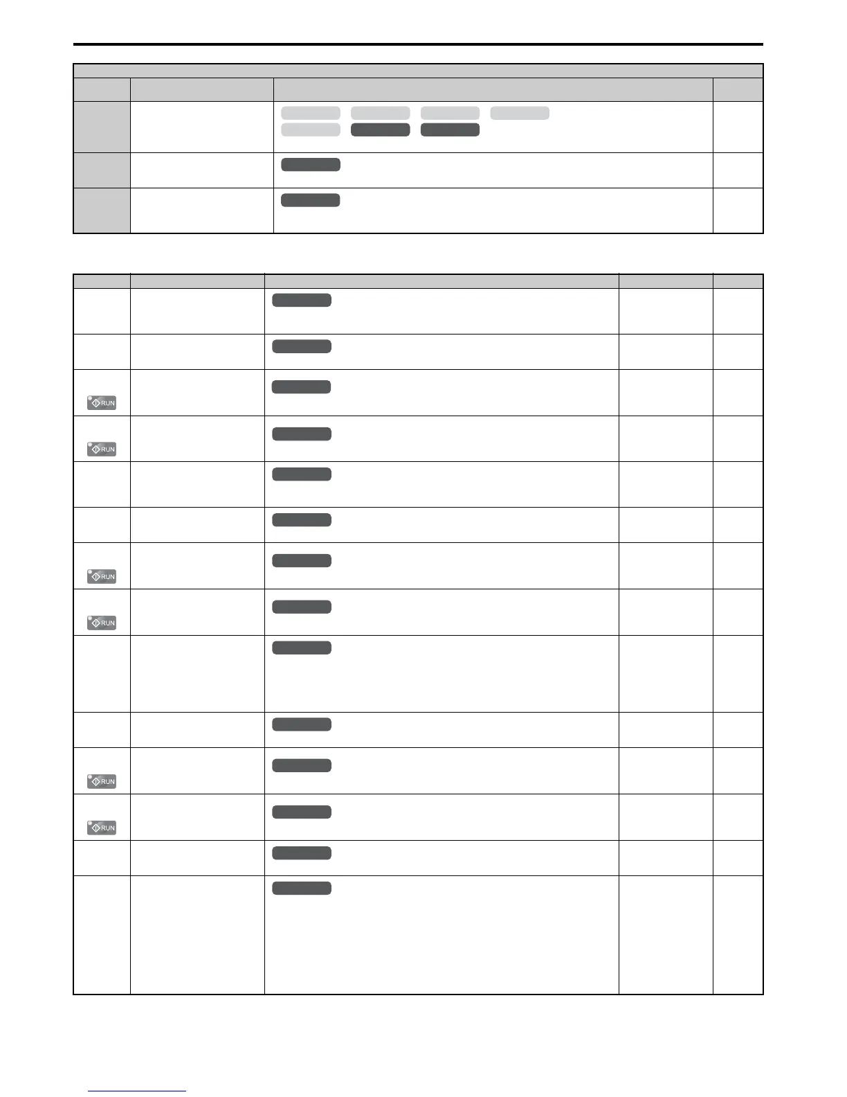
■ H3: Multi-Function Analog Inputs
61 Rotor Position Detection Complete
Closed: Drive has successfully detected the rotor position of the PM motor.
233
90 to 92 DriveWorksEZ Digital Outputs 1 to 3
Reserved for DWEZ digital output functions.
233
100 to 192 Function 0 to 92 with Inverse Output
Inverts the output switching of the multi-function output functions.
Set the last two digits of 1 to reverse the output signal of that specific function.
233
No.(Addr.) Name Description Setting Page
H3-01
(410H)
Terminal A1 Signal Level
Selection
0: 0 to 10 V
1: –10 to 10 V
Default: 0
Min: 0
Max: 1
234
H3-02
(434H)
Terminal A1 Function Selection
Sets the function of terminal A1.
Default: 0
Min: 0
Max: 31
234
H3-03
(411H)
Terminal A1 Gain Setting
Sets the level of the input value selected in H3-02 when 10 V is input at terminal A1.
Default: 100.0%
Min: -999.9%
Max: 999.9%
234
H3-04
(412H)
Terminal A1 Bias Setting
Sets the level of the input value selected in H3-02 when 0 V is input at terminal A1.
Default: 0.0%
Min: -999.9%
Max: 999.9%
234
H3-05
(413H)
Terminal A3 Signal Level
Selection 0: 0 to 10 V
1: –10 to 10 V
Default: 0
Min: 0
Max: 1
235
H3-06
(414H)
Terminal A3 Function Selection
Sets the function of terminal A3.
Default: 2
Min: 0
Max: 31
235
H3-07
(415H)
Terminal A3 Gain Setting
Sets the level of the input value selected in H3-06 when 10 V is input at terminal A3.
Default: 100.0%
Min: -999.9%
Max: 999.9%
236
H3-08
(416H)
Terminal A3 Bias Setting
Sets the level of the input value selected in H3-06 when 0 V is input at terminal A3.
Default: 0.0%
Min: -999.9%
Max: 999.9%
236
H3-09
(417H)
Terminal A2 Signal Level
Selection
0: 0 to 10 V
1: –10 to 10 V
2: 4 to 20 mA
3: 0 to 20 mA
Note: Use DIP switch S1 to set input terminal A2 for a current or a voltage input signal.
Default: 2
Min: 0
Max: 3
236
H3-10
(418H)
Terminal A2 Function Selection
Sets the function of terminal A2.
Default: 0
Min: 0
Max: 31
236
H3-11
(419H)
Terminal A2 Gain Setting
Sets the level of the input value selected in H3-10 when 10 V (20 mA) is input at terminal A2.
Default: 100.0%
Min: -999.9%
Max: 999.9%
236
H3-12
(41AH)
T
ermin
al A2 Bias Setting
Sets the level of the input value selected in H3-10 when 0 V (0 or 4 mA) is input at terminal A2.
Default: 0.0%
Min: -999.9%
Max: 999.9%
236
H3-13
(41BH)
Analog Input Filter Time Constant
Sets a primary delay filter time constant for terminals A1, A2, and A3. Used for noise filtering.
Default: 0.03 s
Min: 0.00 s
Max: 2.00 s
236
H3-14
(41CH)
Analog Input Terminal Enable
Selection
Determines which of the analog input terminals will be enabled when a digital input
programmed for “Analog input enable” (H1- = C) is activated.
1: Terminal A1 only
2: Terminal A2 only
3: Terminals A1 and A2 only
4: Terminal A3 only
5: Terminals A1 and A3
6: Terminals A2 and A3
7: All terminals enabled
Default: 7
Min: 1
Max: 7
237
H2 Multi-Function Digital Output Settings
H2-
Setting
Function Description Page

 Loading...


