2.2 Mechanical Installation
44 YASKAWA ELECTRIC SIEP C710616 27C YASKAWA AC Drive A1000 Technical Manual
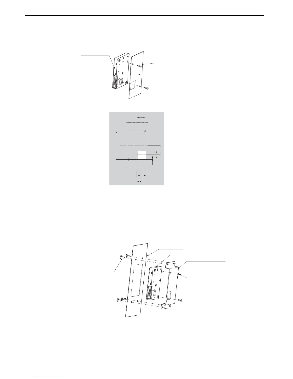
External/Face-Mount
1. Cut an opening in the enclosure panel for the digital operator as shown in Figure 2.8.
2. Position the digital operator so the display faces outwards, and mount it to the enclosure panel as shown in
Figure 2.7.
Figure 2. 6
Figure 2.7 External/Face-Mount Installation
Figure 2. 7
Figure 2.8 Panel Cut-Out Dimensions (External/Face-Mount Installation)
Internal/Flush-Mount
An internal flush-mount requires an installation support set that must be purchased separately. Contact your Yaskawa
representative to order an installation support set and mounting hardware. Figure 2.9 illustrates how to attach the
Installation Support Set A.
1.
Cut an opening in the enclosure panel for the digital operator as shown in Figure 2.10.
2. Mount the digital operator to the installation support.
3. Mount the installation support set and digital operator to the enclosure panel.
Figure 2. 8
Figure 2.9 Internal/Flush Mount Installation
Note: For environments with a significant amount of dust or other airborne debris, use a gasket between the enclosure panel and the
digital operator.
Enclosure panel
Unit: mm
Digital Operator
Installation Support Set A
M4 × 10
Phillips truss head screw × 4
(for panel widths between 1 and 1.6)
M3 × 6
Phillips recessed
pan head machine screw × 2

 Loading...


