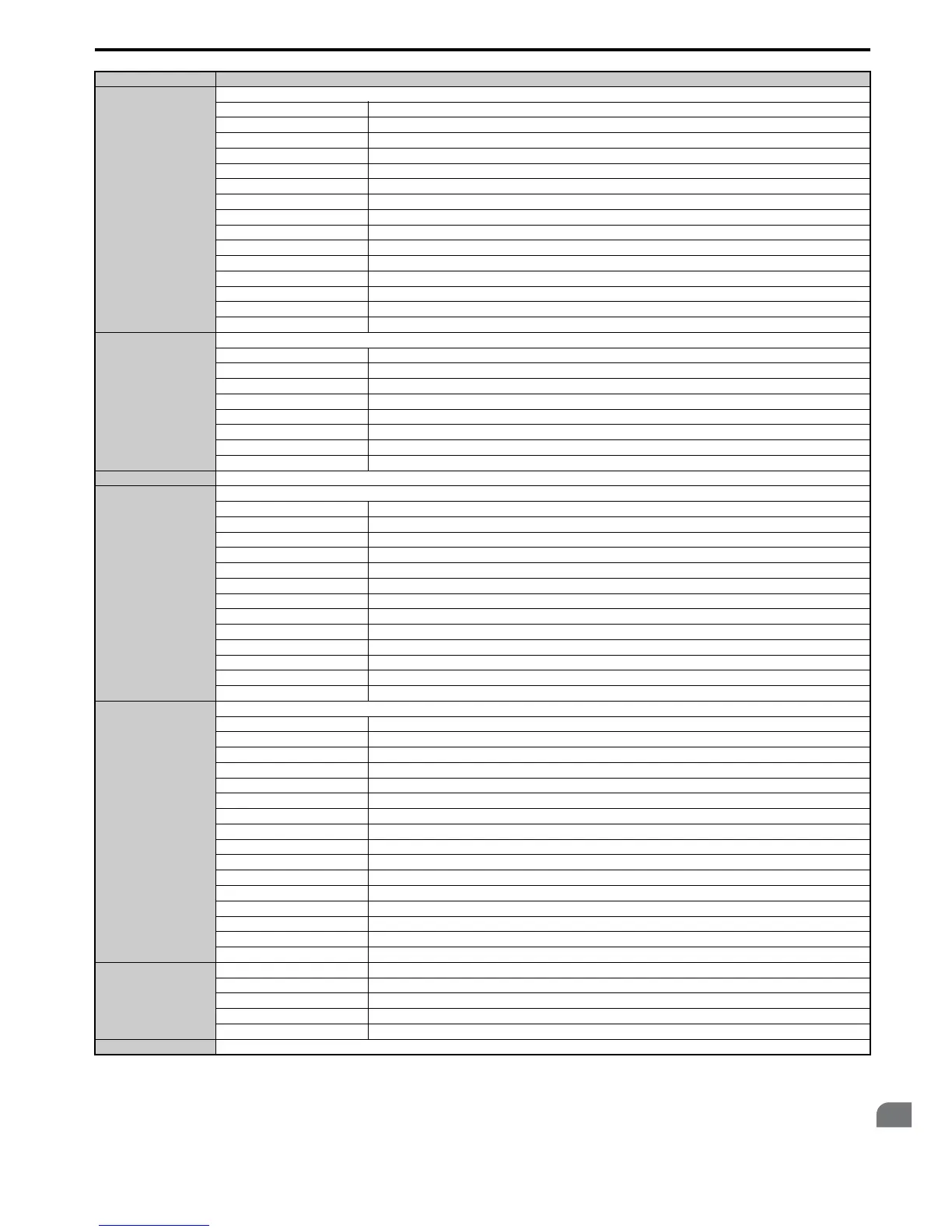
00CBH
Alarm Contents 5
bit 0 SI-T3 Watchdog Error (E5)
bit 1 SI-T3 Station Address Setting Error (AEr)
bit 2 SI-T3 Comm. Cycle Setting Error (CyC)
bit 3 High Current Alarm (HCA)
bit 4 Cooling Fan Maintenance Time (LT-1)
bit 5 Soft Charge Bypass Relay Maintenance Time (LT-2)
bit 6 Reserved
bit 7 SI-S EEPROM Error (EEP)
bit 8 External Fault 1 (input terminal S1) (EF1)
bit 9 External Fault 2 (input terminal S2) (EF2)
bit A Safe Disable Input (HbbF)
bit B Safe Disable Input (Hbb)
bit C Mechanical Weakening Detection 1 (oL5)
bit D Mechanical Weakening Detection 2 (UL5)
bit E, F Reserved
00CCH
Alarm Contents 6
bit 0 Output Voltage Detection Fault (VoF)
bit 1 IGBT Maintenance Time (90%) (TrPC)
bit 2 Capacitor Maintenance Time (LT-3)
bit 3 IGBT Maintenance Time (50%) (LT-4)
bit 4 Braking Transistor Overload Fault (boL)
bit 5 to 7 Reserved
bit 8 DriveWorksEZ Alarm (dWAL)
bit 9 to F Reserved
00CDH to 00CFH Reserved
00D0H
CPF Contents 1
bit 0, 1 Reserved
bit 2 A/D Conversion Error (CPF02)
bit 3 PWM Data Fault (CPF03)
bit 4, 5 Reserved
bit 6 EEPROM Memory Data Error (CPF06)
bit 7 Terminal Board Connection Error (CPF07)
bit 8 EEPROM Serial Communications Fault (CPF08)
bit 9, A Reserved
bit B RAM Fault (CPF11)
bit C FLASH Memory Fault (CPF12)
bit D Watchdog Circuit Exception (CPF13)
bit E Control Circuit Fault (CPF14)
bit F Reserved
00D1H
CPF Contents 2
bit 0 Clock Fault (CPF16)
bit 1 Timing Fault (CPF17)
bit 2 Control Circuit Fault (CPF18)
bit 3 Control Circuit Fault (CPF19)
bit 4 Hardware fault at power up (CPF20)
bit 5 Hardware fault at communication start up (CPF21)
bit 6 A/D Conversion Fault (CPF22)
bit 7 PWM Feedback Fault (CPF23)
bit 8 Drive Unit Signal Fault (CPF24)
bit 9 Terminal board is not properly connected. (CPF25)
bit A ASIC BB Circuit Error (CPF26)
bit B ASIC PWM Setting Register Error (CPF27)
bit C ASIC PWM Pattern Error (CPF28)
bit D ASIC On-delay Error (CPF29)
bit E ASIC BBON Error (CPF30)
bit F ASIC Code Error (CPF31)
00D2H
bit 0 ASIC Start-up Error (CPF32)
bit 1 Watch-dog Error (CPF33)
bit 2 ASIC Power/Clock Error (CPF34)
bit 3 External A/D Converter Error (CPF35)
bit 4 to F Reserved
00D3H to 00D7H oFA0x Contents (CN5-A)
Register No. Contents

 Loading...


