5 Replacing Parts
DX100 5.1 Replacing DX100 Parts
5-13
9. Remove screws fixing the amplifier.
*03 to 21 amplifier: Remove upper right and lower left screws
(2 places).
*35 to 71 amplifier: Remove IPM fixing screws (2 places) besides t
upper right and lower left screws (2 places).
10. Mount thermal sheet to the new servo amplifier.
(Refer to Thermal Sheet Mounting Instruction.)
11. Mount the new amplifier.
12. Connect all the disconnected cables to the new amplifier.
13. Tighten two EAXA base fixing screws. (upper side)
14. Tighten two EAXA base fixing screws. (lower side)
15. Connect all the disconnected cables to the servopack.
Refer to the reversed procedures described in step 3.
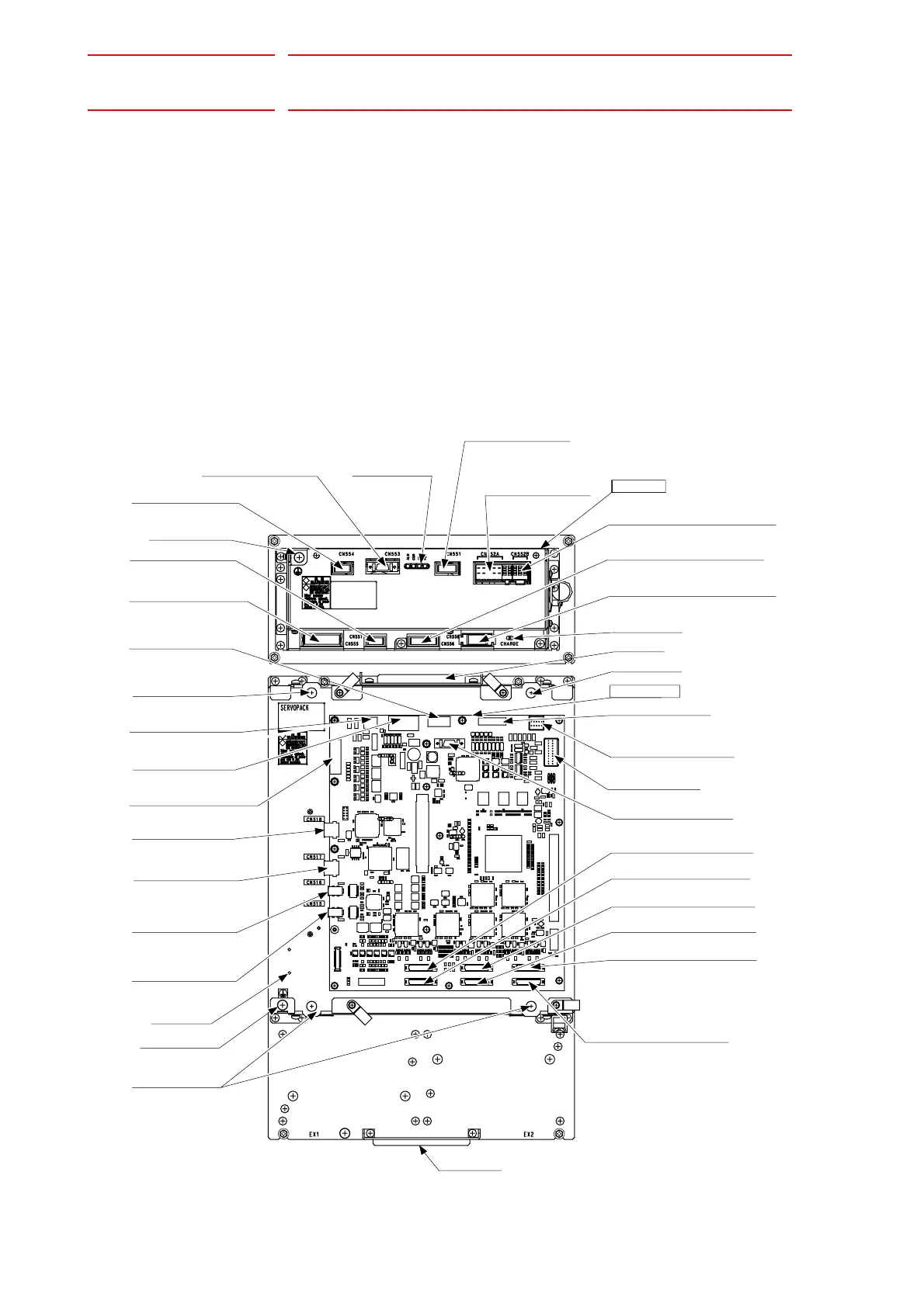
SERVOPACK
EAXA board
Converter
AMP2 PWM signal connector
(CN502)
(CN501)
AMP1 PWM signal connector
AMP3 PWM signal connector
(CN503)
AMP4 PWM signal connector
(CN504)
AMP6 PWM signal connector
AMP5 PWM signal connector
(CN505)
(CN506)
EAXA base
EAXA base fixing
screw (bottom)
(CN516)
(CN518)
SHOCK signal input
connector
(CN512)
Control power supply
output connector for
converter
(CN510)
(CN513)
Connector for brake
control signal
Main circuit power supply output
connector for external axis amplifie
Upper grip
Ground terminal
Charge lamp
Monitor / Alarm
displaying LED
Connector for control
power supply input
(CN551)
(CN552A)
(CN552B)
Ground terminal
Lower grip
(CN507)
Connector for converter
control signal
(CN511)
Safety unit I/F connector
(CN514)
Direct-in connector
(CN517)
Control communication
connector
(CN515)
(CN508)
Connector for encoder
signal
(CN509)
Connector for control
power supply input
(CN556)
(CN558)
Connector for connecting
regenerative resistor
Connector for main
circuit power supply input
(CN557)
(CN555)
Connector for
grounding detection input
Connector for converter
control signal
(CN554)
(CN553)
Control communication
connector
I/O communication
connector
Control communication
connector
EAXA base fixing
screw (upper)
Control power supply
output connector for
6-axis amplifier
EAXA base fixing
screw (upper)
Main circuit power supply output
connector for 6-axis amplifier
Control power supply output
connector for external axis amplifier

 Loading...


