CHAPTER 4 SPECIFICATIONS
Electrical Interface
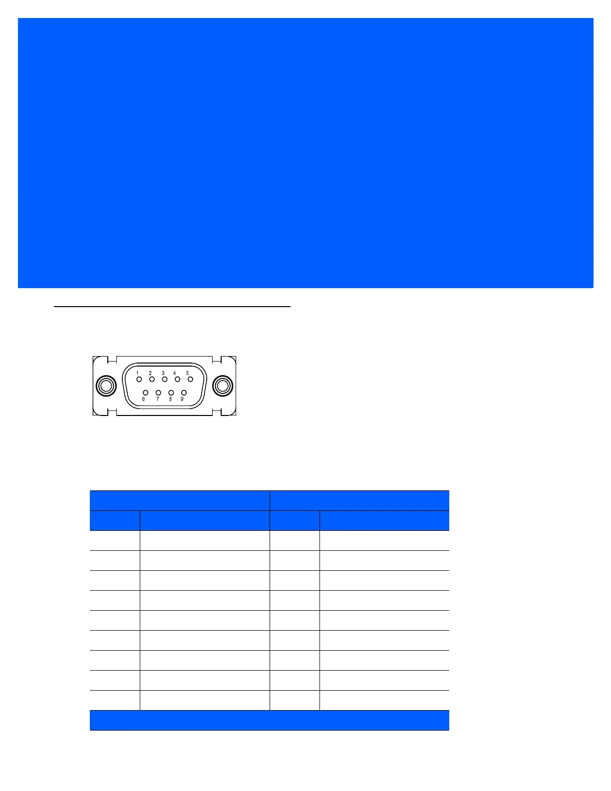
Figure 4-1
DS457 Connector
Table 4-1 lists the pin functions of the DS457 interface.
Table 4-1
DS457 USB and Serial Electrical Interface
USB Interface Serial Interface
Pin No. Pin Name Pin No. Pin Name
1 Trigger 1 Trigger
2 NC 2 TXD Output TTL Only
3 USB + 3 RXD Input TTL Only
4 Connect to Pin 8 4 NC
5 Ground 5 Ground
6 +5V Power 6 +5V Power
7 USB - 7 CTS Input TTL Only
8 Connect to Pin 4 8 RTS Output TTL Only
9 Beeper/Download 9 Beeper/Download
NC = No Connect (do not connect this pin)
 Loading...