Technical Specifications
241
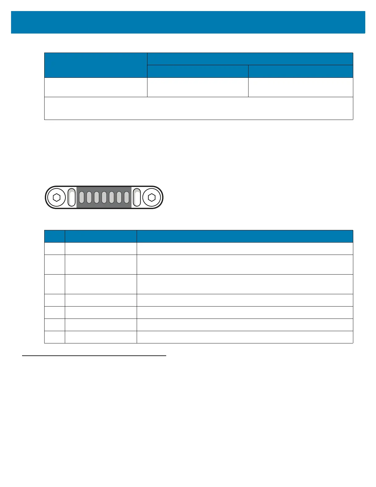
MC33XX Connector Pin-Out
Figure 159 I/O Connector
MC33XX Accessory Specifications
The following sections provide technical specifications for the MC33XX accessories.
15 mil Code 128 (4 in. wide) 8.0 in. *
20.3 cm *
100.0 in.
254.0 cm
NOTE: * Limited by width of bar code in field of view.
** Range is reduced under low ambient light level.
Table 24 SE4850-ER Decode Distances (Continued)
Symbol Density/ Barcode Type
Typical Working Ranges @20 Ft-Cd Minimum
Near Far
Table 25 I/O Connector Pin-Outs
Pin Signal Name Description
1 Ground Ground pin connected to the Cradle or USB Charge Cable ground.
2 USB ID Identification signal for USI OTG communication (USB ID) which determines
USB mode (host or device).
3POWER_IN_CON
(9V/1.5A or 5V/2Amax)
DC Power supply from the Cradle.
4 USB PWR Power supply from USB Charging Cable.
5 USB D- USB OTG data signal negative.
6 USB D+ USB OTG data signal positive.
7 GND Ground pin connected to the Cradle or USB Charge Cable ground.
 Loading...