6. Interrupt controller A96G166/A96A166/A96S166 User’s manual
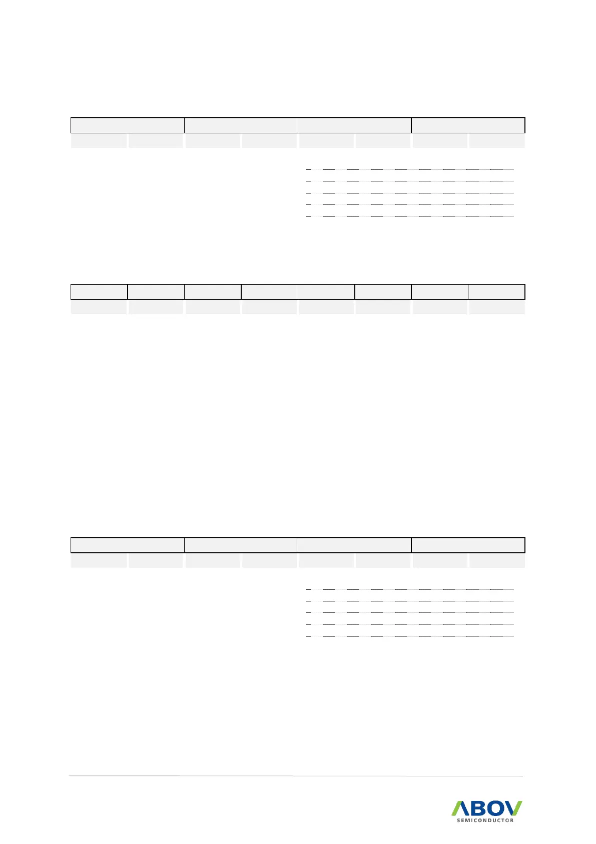
EIPOL0H (External Interrupt Polarity 0High Register): A5H
External interrupt (EINT6, EINT5, EINT4) polarity selection
Interrupt on falling edge
Interrupt on both of rising and falling edge
EIFLAG1 (External Interrupt Flag 1 Register): A6H
When T0 interrupt occurs, this bit becomes ‘1’. For clearing bit,
write ‘0’ to this bit or auto clear by INT_ACK signal. Writing “1” has
no effect.
T0 interrupt no generation
When an External Interrupt 10 ~ 12 is occurred, the flag becomes
‘1’.The flag is cleared only by writing ‘0’ to the bit or automatically
cleared by INT_ACK signal. Writing “1” has no effect.
External interrupt 10 ~ 12 not occurred
External interrupt 10 ~ 12 occurred
When an External Interrupt 7 ~ A is occurred, the flag becomes
‘1’.The flag is cleared only by writing ‘0’ to the bit. So, the flag
should be cleared by software. Writing “1” has no effect.
External interrupt 7 ~ A not occurred
External interrupt 7 ~ A occurred
EIPOL1 (External Interrupt Polarity 1 Register): A7H
External interrupt (EINT12,EINT11,EINT10) polarity selection
Interrupt on falling edge
Interrupt on both of rising and falling edge