Inlets and valves
6850
6850
Released: April 2004 6850 Series Gas Chromatograph Service Procedures 132
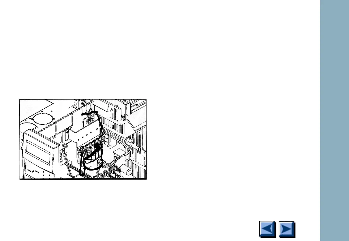
2. Unplug the connectors on the valve driver
cable harness out from the slots on the valve
driver bracket.
Unplug the larger 2 × 2 heater sensor
connectors (P1, P2) into the outside slots
and the smaller 1 × 2 valve driver connec-
tors (P3 to P6) into the four middle slots.
Figure 1-53. Installing the cabling
3. Unplug in the heater/sensor lead(s) from the
valve heater blocks on top of the GC.
Remove the heater/sensor lead(s) to the right
side of the instrument, out of one of the key-
hole wiring slots and into the P1 or P2 detec-
tor on the actuator bracket.
4. Reassemble with new parts in reverse order.
Replacing the drivers on the valve driver
block
1. Use a hex wrench to unscrew the two hex
screws on the left side of the block. Remove
the driver, collapse the block to the width of
the remaining drivers and reinstall the hex
screws.
2. Slide the new valve driver block into the
driver bracket until the drivers plug into the
connectors.

 Loading...


