Inlets and valves
6850
6850
Released: April 2004 6850 Series Gas Chromatograph Service Procedures 87
4. Remove the RFI shield and the top rear cover
on the GC.
5. Disconnect the ribbon cable for the module
from the main EPC board. You may have to
remove the adjacent ribbon cable also.
6. Use a Torx T-20 screwdriver to remove the
screw from the top of the module and slide
the module out of the back of the GC.
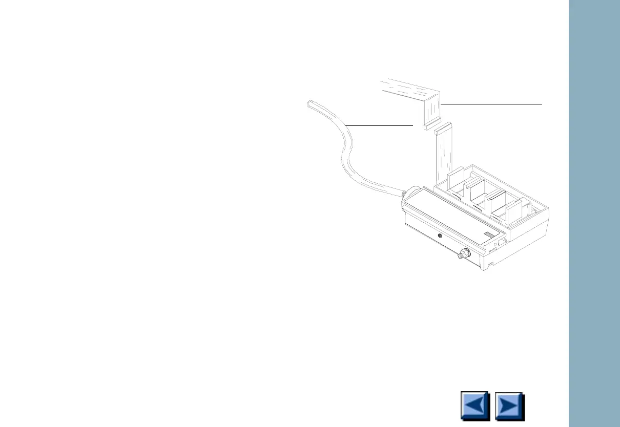
7. Connect one end of the leak test ribbon cable
(G1530-61370) to the ribbon cable connec-
tor on the EPC module and connect the other
end to the appropriate connector on the EPC
board.
8. Reconnect the carrier supply fitting and set
pressures as used in the leak test.
9. Lay the EPC module on the lab bench and use
an electronic leak detector to locate the
leaky component on the module.
Figure 1-25. Leak testing the EPC module on
the lab bench
To gas supply
Ribbon cable from
leak test kit

 Loading...


