14 Rockwell Automation Publication 6000-TD004D-EN-P - November 2017
Chapter 1 Functional Descriptions
Ramp
This function includes the S curve setting, frequency dead zone setting, and
frequency amplitude limit.
The S curve setting means integral setting on frequency signal, also known as the
ramp setting. In PowerFlex 6000 drives, the curve is used to set the motor’s speed.
The ramp curve in S curve can avoid the over current and over voltage faults by
reducing the increasing or decreasing speed. Also, the rounded corners in S curve
can reduce the impact on mechanical components.
• Deceleration-time “Td” is determined by the formula:
Deceleration Time (P399) * Deceleration Time Unit (P406)
This value should be adjusted according to the actual case. An
inappropriate setting will result in an input voltage over-voltage fault in the
power cell.
• Deceleration-rounded-corner-time “Trd” is determined by the formula:
Deceleration Ramp Transition Time (P405) * Deceleration Time Unit
(P406)
In most cases, the default value need not be changed.
• Acceleration-time “Tu” is determined by the formula:
Acceleration Time (P401) * Acceleration Time Unit (P403)
This value should be adjusted according to the actual case. An
inappropriate setting will result in an over-current fault.
• Acceleration-rounded-corner-time “Tru” is determined by the formula:
Acceleration Ramp Transition Time (P402) * Acceleration Time Unit
(P403)
In most cases, the default value need not be changed.
• Amplification Coefficient Of Error Terms (P409) is also used.
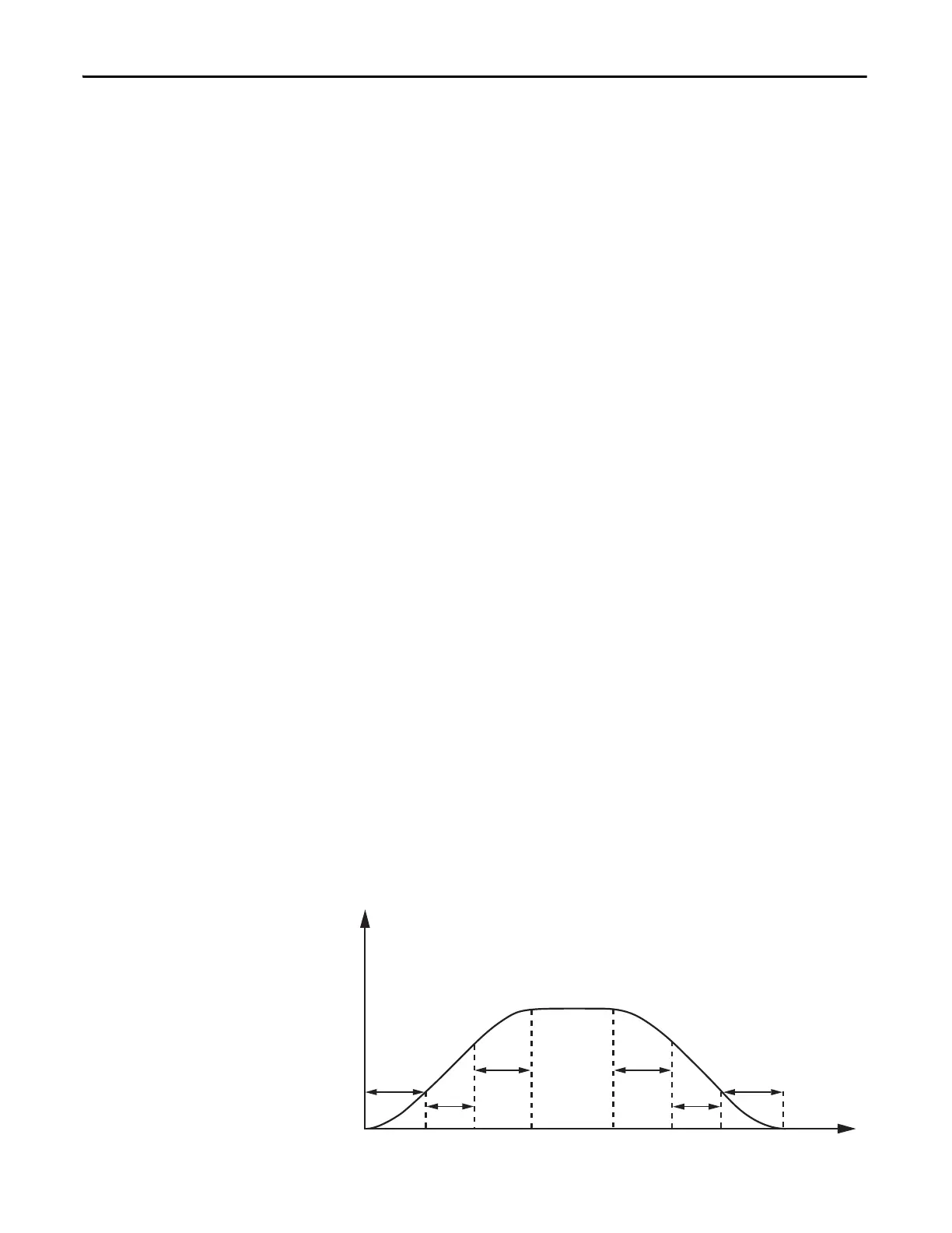
See the following diagram for the explanation of the different time settings.
Figure 1 - S Curve Diagram
Frequency
Tru
Tu
Td
Tru
Trd
Trd

 Loading...


