Rockwell Automation Publication 6000-TD004D-EN-P - November 2017 211
Warning Messages Chapter 4
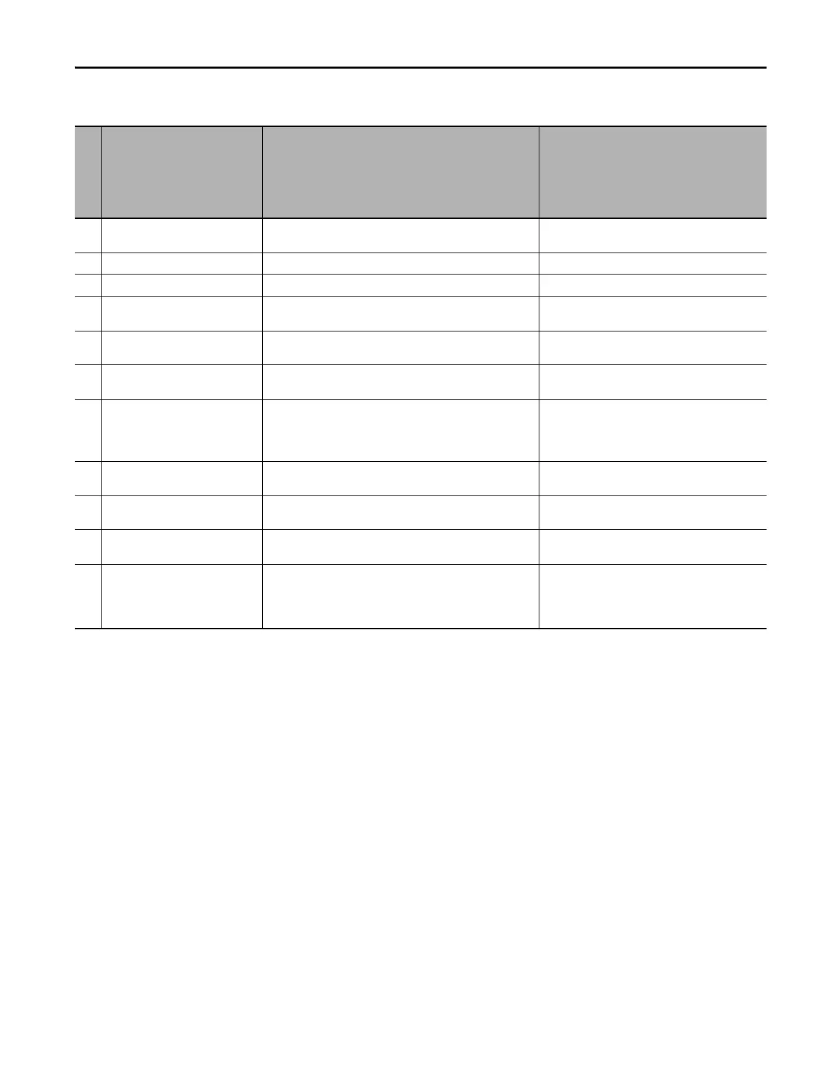
Logic Warning
No. Logic Warning Message Description Recommended Action(s)
16 DSP Communication Error There is a communication error between the PLC and DSP. • Check connection between the drive and PLC.
• Check receive and transmit LED status on CPU board.
17 PLC Communication Error There is a communication error between the PLC and HMI. Check connection between the HMI and PLC.
18 HMI Version Incompatible The versions of the HMI and PLC are not compatible. Check the versions of the HMI and PLC.
19 Transformer Over Temperature Warning The transformer is over temperature. • Check the transformer and transformer cabinet fan.
• Check configuration of the transformer monitor.
20 Power Cell Cabinet Fan Circuit Breaker
Open
This warning appears when the MV is energized while the power cell
cabinet fan circuit breaker is open.
Check the power cell cabinet fan circuit breaker. It should
be closed before the MV is energized.
21 Transformer Cabinet Fan Circuit Breaker
Open
This warning appears when the MV is energized while the transformer
cabinet fan circuit breaker is open.
Check the transformer cabinet fan circuit breaker. It
should be closed before the MV is energized.
22 External Control Power Loss Warning Control power usually comes from the user side and the transformer
acts as a backup.
This warning appears when the user side does not supply control
power and the transformer is used.
• Check user side control power.
• Check status of UPS.
23 Analog Channel #1 Loss Warning There is signal loss in analog channel #1 (4-20 mA). • Check wiring of analog channel #1.
• Check if 4-20 mA signal from user side is present.
24 DCS Communication Error Warning This warning appears if the control mode is set to DCS (Owner #2
Selection (P476) = 15) and DCS communication is interrupted.
Check communication cable between the user side and
drive.
25 Analog Feedback Loss Warning This warning appears when the PID function is enabled and there is no
analog feedback.
• Check wiring between the user side and drive.
• Check if 4-20 mA signal from user side is present.
26 Analog Channel #2 Loss Warning There is signal loss in analog channel #2 (4-20 mA).
Analog channel #2 is the analog signal input backup.
When User Analog Set-point Switch (P494) = 1, this analog channel is
used as the 4-20 mA input.
• Check wiring of analog channel #2.
• Check if 4-20 mA signal from user side is present.

 Loading...


