Rockwell Automation Publication 6000-TD004D-EN-P - November 2017 19
Functional Descriptions Chapter 1
Table 3 - Digital Output Signal Parameter Setting Group
Analog Output
This function is used to set the analog output channel. The analog signal can be
output into 0-5V voltage or 4-20 mA current. There are four analog output
channels available in PowerFlex 6000 drives – one for actual frequency variant,
one for stator current variant, and the rest are reserved.
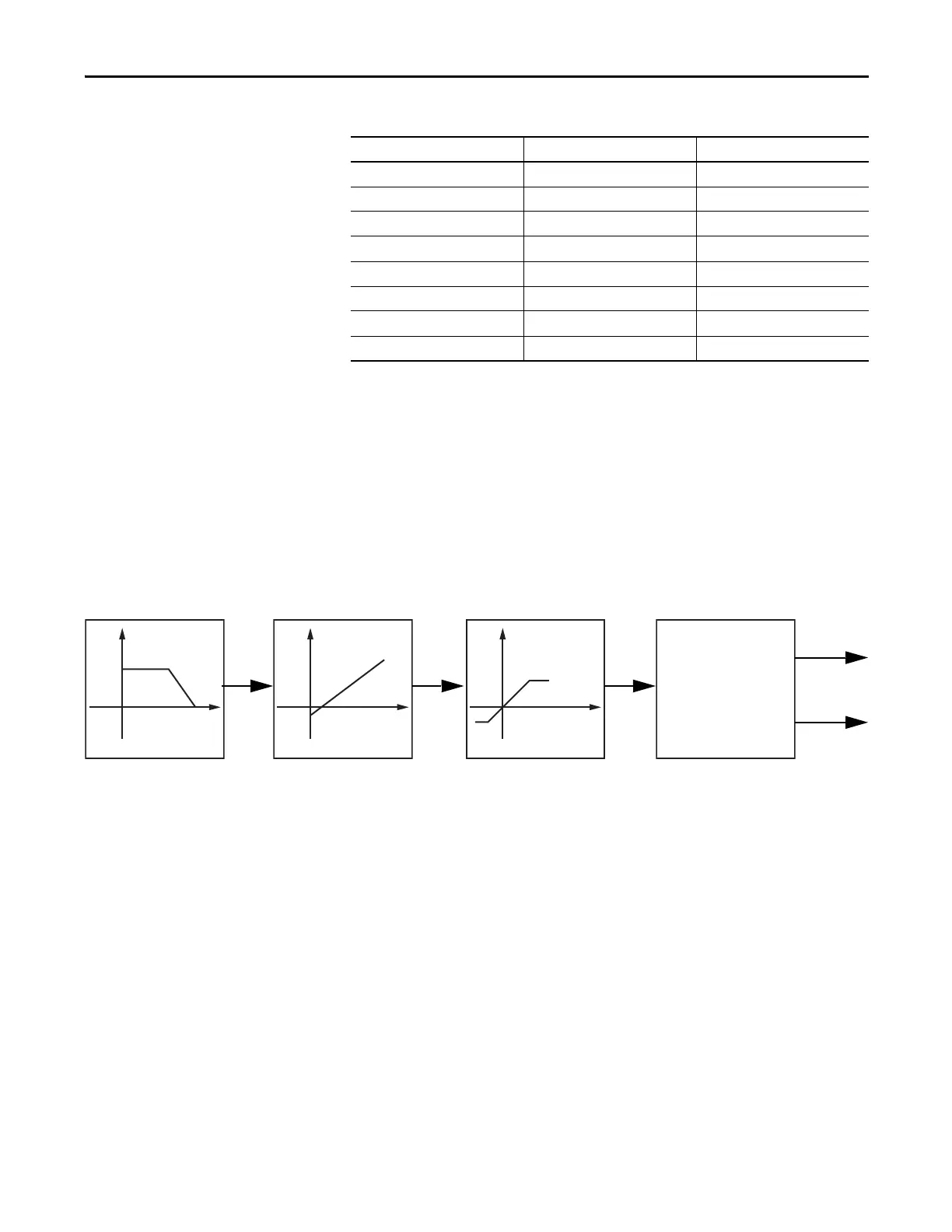
The selected variant will undergo a Low-Pass Filter, Amplitude-correction, and
Amplitude-limitation process before the final result is output as a 0-5V and 4-20
mA analog signal. See the following diagram for the process.
Figure 3 - Analog Output Function Diagram
The actual frequency was filtered through the Low-Pass Filter with the filter time
set to one second, amplitude scaling factor to 50%, offset to zero, and the output
channel number is one.
Analog Output #1 Memory Address (P332) = 252
Analog Output #1 Filter Time (P333) = 1000 ms
Analog Output #1 Offset (P334) = 0
Analog Output #1 Scaling Factor (P335) = 50.00%
Hardwired I/O Interface Description Related Parameters
I/O0 High voltage can be closed P300, P301, P302, P303
I/O1 System running P304, P305, P306, P307
I/O2 System fault P308, P309, P310, P311
I/O3 System trip P312, P313, P314, P315
I/O4 Warning P316, P317, P318, P319
I/O5 Warning bell P320, P321, P322, P323
I/O6 Customized trip P324, P325, P326, P327
I/O7 Pre-charge complete P328, P329, P330, P331
Low-pass Filter
Y = x / (P333 * s + 1)
Linear Transformation
Y = P335 * (x +P334)
Digital/Analog
Transformation

 Loading...


