204 Rockwell Automation Publication 6000-TD004D-EN-P - November 2017
Chapter 3 Fault Messages
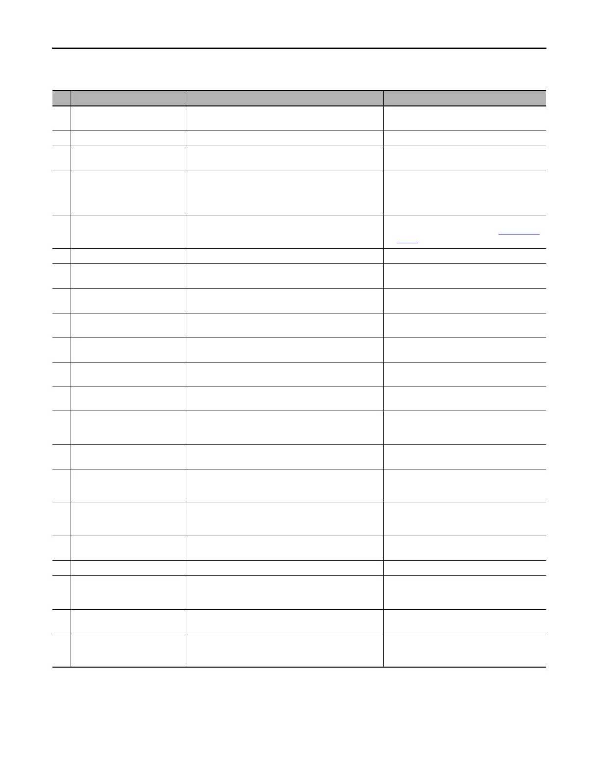
Logic Faults
No. Logic Fault Message Description Recommended Action(s)
24 Cabinet Door Opened While Drive
Energized
The cabinet door has been opened while the drive input contactor is
closed.
• Check cabinet door.
• Check feedback signal of contactor.
25 E-Stop Trip The emergency stop button was pressed. Check the emergency stop button.
26 Input Circuit Breaker Opened
(Not Initiated by the Drive)
This fault occurs if the input circuit breaker is opened while the drive is
running.
• Verify if the contactor is open.
• Check feedback signal of contactor.
27 Non-Zero Frequency Command Exists
Upon Start
This is a safety start option and not an actual fault.
If Safe Start Condition (P040) is set to “0” (Zero Frequency Command
Required), then the frequency must be set to zero before starting the
drive.
Check parameter Safe Start Condition (P040) is set
correctly.
28 Flying Start Failed This fault occurs if the Flying Start function is enabled and the drive is
unable to detect the motor speed until the scan frequency is zero.
• Check the parameters are set correctly.
• Adjust the parameters as described in Flying Start
on
page 35.
29 System Locked If any other fault has occurred, this fault appears as a message flag. Verify the fault on the HMI.
30 CPU Board in Wrong Position The CPU board address does not match the CPU board address set on
the DB board.
Verify the position of the CPU board and make sure it is
plugged in firmly.
31 AT Board in Wrong Position The AT board address does not match the AT board address set on the
DB board.
Verify the position of the AT board and make sure it is
plugged in firmly.
32 5V Power Supply Fault The voltage between 5V to M1 of Phoenix terminal P1 is out of range
(4.31...5.52V).
Check the voltage between 5V to M1 on Phoenix terminal
P1.
33 15V Power Supply Fault The voltage between +15V TEST point to M5 of Phoenix terminal P1 is
out of range (12.95...16.56V).
Check the voltage between +15V to M5 on Phoenix
terminal P1.
34 24V DCS Power Supply Fault The voltage between 24V1 to M4 of Phoenix terminal P2 in the control
box is out of range (21.22...26.50V).
Check the voltage between 24V1 to M4 on Phoenix
terminal P2.
35 24V PLC Power Supply Fault The voltage between 24V3 to M2 of Phoenix terminal P2 in the control
box is out of range (21.22...26.50V).
Check the voltage between 24V3 to M2 on Phoenix
terminal P2.
36
...
38
PWMx Board in Wrong Position
(x = A, B or C)
The PWMx board address does not match the PWMx (A, B, or C) board
address set on the DB board.
Verify the position of the PWMx (A, B, or C) board and
make sure it is plugged in firmly.
39 DT Board in Wrong Position The DB board address does not match the DB board address set on the
DB board.
Verify the position of the DB board and make sure it is
plugged in firmly.
40 Low Voltage Ride Through Over Max
Time Limit
The low voltage duration is longer than the maximum value of Low
Voltage Ride Through Max Time Limit (P285).
• Check parameter Low Voltage Ride Through Max Time
Limit (P285) is set correctly.
• Verify the duration of input voltage sag.
41 Low Voltage Ride Through Short
Interval (Between Two Ride Through)
The LVRT function has been triggered twice and the time interval
between these two events is shorter than the minimum value of Low
Voltage Ride Through MinFrequency Limit (P281).
• Check parameter Low Voltage Ride Through
MinFrequency Limit (P281) is set correctly.
• Verify the duration of input voltage sag.
42 Low Voltage Ride Through Failure The LVRT function did not receive enough information to ride through
the low voltage state.
• Verify the duration of input voltage sag.
43 Input Voltage Loss While Stop Voltage is lost while the drive is stopping. Check the input voltage record.
44 Input Voltage Loss Over Time Limit The duration of input voltage loss is longer than the maximum value
set in Power Loss AllowableTime (P264). Power Loss AllowableTime-
User Defined cannot be higher than PowerLoss Time Max Limit (P265).
• Check parameters
Power Loss AllowableTime (P264)
and PowerLoss Time Max Limit (P265) are set correctly.
• Verify the duration of input voltage loss.
45 Input Voltage Loss Line side voltage loss is present and the power loss function is
disabled.
Check if input voltage (before user breaker) has been lost.
If not, verify the power loss relay state.
46 Cell Bypass Timeout After a cell bypass is triggered, the drive failed to start within the
duration set in Low Voltage Ride Through Max Time Limit (P285).
• Check hardware of the power cell.
• Check parameter Low Voltage Ride Through Max Time
Limit (P285) is set correctly.

 Loading...


