Rockwell Automation Publication 6000-TD004D-EN-P - November 2017 39
Functional Descriptions Chapter 1
• Low Speed Voltage Compensation (P451)
• Low Speed Voltage Compensation Threshold (P464)
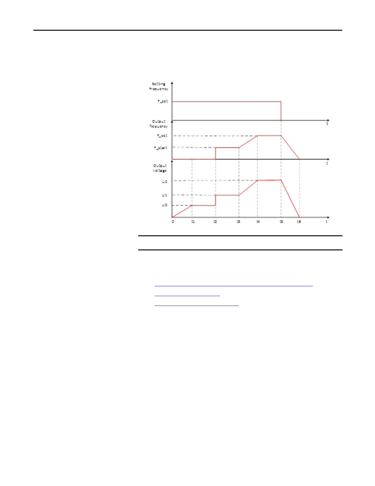
Figure 16 - Start and Stop Sequence Diagram
Process Control
The process control settings include the following functions:
• Deceleration and Acceleration Process User Define
on page 39
• PID Function on page 41
• Deceleration Control on page 42
Deceleration and Acceleration Process User Define
This function allows you to define the deceleration and acceleration process into
four steps to suit your application.
The drive decelerates from rated frequency to Freq1 during t1, from Freq1 to
Freq2 during t2, from Freq2 to Freq3 during t3, and from Freq3 to zero during t4.
The following parameters are used to define the deceleration process:
• Freq1 = Deceleration Frequency 1 (P387)
• Freq2 = Deceleration Frequency 2 (P389)
• Freq3 = Deceleration Frequency 3 (P391)
• t1 = Deceleration Time 1 (P386)
• t2 = Deceleration Time 2 (P388)
It is recommended to use these functions when the drive is not in SVC mode.

 Loading...


