194 Rockwell Automation Publication 6000-TD004D-EN-P - November 2017
Chapter 2 Parameter Descriptions
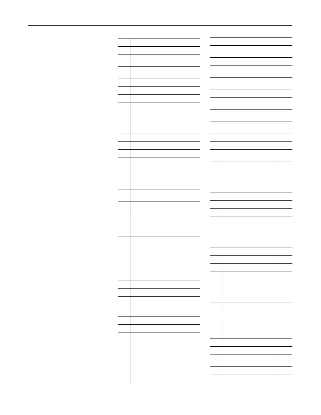
Linear Number Index
No. Parameter Name Page
P007 Number of Power Cells Per Phase 49
P008 Motor Rotation Direction Under Local
Control
64
P009 Motor Rotation Direction Command
Selection
64
P011 Power Cell DC Bus Rated Voltage 50
P012 Motor Rated Voltage 50
P013 Motor Rated Power 50
P014 Motor Rated Speed 50
P015 Motor Rated Power Factor 51
P017 Number of Motor Pole Pairs 51
P019 Encoder Resolution 51
P024 Stop Method 63
P030 Powercell Fault Trip Signal Mask 93
P031 System Fault Trip Signal Mask 94
P034 Current Stability Loop Filter Time 111
P035 Current Stability Loop Frequency
Range1 Output Scaling Factor
111
P036 Current Stability Loop Output Upper
Limit
111
P037 Current Stability Loop Output Lower
Limit
111
P038 Current Stability Loop Enable 112
P039 Current Stability Loop Enable Frequency
Range1 Upper limit
112
P040 Safe Start Condition 54
P041 Power Cell Bypass Enable 103
P042 Power Cell Bypass Delay After Power Cell
Bypassed
103
P043 Power Cell Bypass Upper Limit For
Bypassed Feedback Time
104
P044 Power Cell Bypass Fault Simulation
Power Cell Count
104
P045 Load Loss Control Enable 117
P046 Load Loss Enable Frequency 117
P047 Load Loss Control Differential Scaling 117
P048 Load Loss Frequency Compensation
Upper Limit
117
P049 Load Loss Control Scaling Factor 118
P050 Load Loss Control Integral Time 118
P051 Load Loss Control Filter Time 118
P052 Load Loss Enable Current Threshold 118
P053 Load Loss Control Exit Delay 119
P057 Power Cell Bypass Upper Limit Time For
Over Temperature
104
P058 Power Cell Bypass Phase A Cell Number
For Simulation
104
P059 Power Cell Bypass Phase B Cell Number
For Simulation
105
P060 Power Cell Bypass Phase C Cell Number
For Simulation
105
P061 Power Cell Bypass Fault Simulation 105
P065 Power Cell Bypass Enable Frequency
Range Lower limit
105
P066 Power Cell Bypass Restart Enable After
Power Cell Bypassed
106
P068 One Phase Lost Filter Time 106
P069 Current Stability Loop Enable Frequency
Range2 Upper Limit
112
P070 Current Stability Loop Frequency
Range2 Output Scaling Factor
112
P071 Current Stability Loop Frequency
Range3 Output Scaling Factor
113
P072 Current Stability Loop Enable Delay 113
P073 Input Voltage Loss Filter Time 102
P078 Power Cell Reactivation Time Upper
Limit
106
P079 VFD Minimum Overload Current 135
P080 VFDOverload Current 135
P081 VFD Overload Time 135
P082 VFD Overload Cycle Time 135
P085 VFD Rated Current 51
P087 Switch Frequency Setting Enable Code 65
P088 Switch Frequency Setting 65
P089 Skip Frequency Enable 126
P090 Skip Frequency 1 Lower Limit 126
P091 Skip Frequency 1 Upper Limit 126
P092 Skip Frequency 2 Lower Limit 126
P093 Skip Frequency 2 Upper Limit 127
P094 Fan Control Mode 88
P095 Fan Control Group #1 Fan Number 88
P096 Fan Control Group #2 Fan Number 88
P097 Fan Control Group #3 Fan Number 88
P098 Fan Control Group #4 Fan Number 89
P099 Fan Control Main Cooling Fan Cycle Time 89
P100 Fan Control Redundant Fan Working
Time
89
P101 Fan Control Fan Feedback Delay 89
P102 Fan Control Fan Stop Delay 90
P103 Pre-charge Enable 91
P104 Pre-charge Feedback Delay 91
P105 Pre-charge DC Bus Threshold 92
P106 Fan Control Transformer Cabinet Fan
Quantity Upper Limit
90
P107 VFD Overload Current Offset 136
P108 Motor Overload Current Offset 136
No. Parameter Name Page

 Loading...


