20 Rockwell Automation Publication 6000-TD004D-EN-P - November 2017
Chapter 1 Functional Descriptions
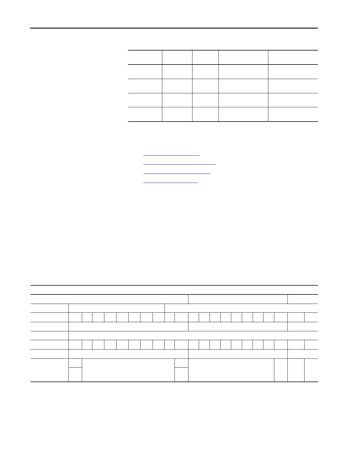
Table 4 - Analog Output Display Parameter Setting Group
Drive Configuration
The drive configuration include the following functions:
• Fan Control
on page 20
• Pre-charge Control on page 23
• Customized Trip on page 25
• Over Speed on page 26
Fan Control
This function is used to manage heat dissipation in the transformer cabinet, filter
cabinet, and power module cabinet when the drive is running. If the additional
heat generated is not dissipated in time, the drive will trip, or the transformer,
power module, or filter device may be damaged. There are three fan control
modes – non-redundant fan, one fan as redundant fan, all fans work in cycle
mode. Configuring a redundant fan can help to improve reliability of the drive
and reduce downtime.
Table 5 - PLC I/O and K Register Definition
Analog Output Data Storage Parameters Hardwired I/O
Interface (current)
Hardwired I/O
Interface (voltage)
Actual frequency K252 P332, P333,
P334, P335
IoutA equals P11.5
Signal ground equals P11.1
UoutA equals P10.5
Signal ground equals P10.1
System current K206 P336, P337,
P338, P339
IoutB equals P11.6
Signal ground equals P11.2
UoutB equals P10.6
Signal ground equals P10.2
Channel 3 Reserved P340, P341,
P342, P343
IoutC equals P11.7
Signal ground equals P11.3
UoutC equals P10.7
Signal ground equals P10.3
Channel 4 Reserved P344, P345,
P346, P347
IoutD equals P11.8
Signal ground equals P11.4
UoutD equals P10.8
Signal ground equals P10.4
Fan Control I/O Assign
TX Cabinet Fan Control Power Cabinet Filter Cabinet
PLC Module PLC8 PLC9
Fan CMD I/O O-8 O-9 O-10 O-11 O-12 O-13 O-14 O-15 O-0 O-1 O-2 O-3 O-4 O-5 O-6 O-7 O-8 O-9 O-10 O-11 O-12
Register Mapping K201...K202 K203 K204
PLC Module PLC7
Fan Fdb I/O I-1 I-2 I-3 I-4 I-5 I-6 I-7 I-8 I-9 I-10 I-11 I-12 I-13 I-14 I-15 I-16 I-17 I-18 I-19 I-20 I-21
Register Mapping K66 and K67 K68 K69
Fan Type Definition TX1 Main Cooling Fan I/O TX2 Main Cooling Fan I/O R-Fan
I/O
Main
Cooling
Fan
R-Fan
I/O
R-Fan
I/O
R-Fan
I/O

 Loading...


