Rockwell Automation Publication 6000-TD004D-EN-P - November 2017 41
Functional Descriptions Chapter 1
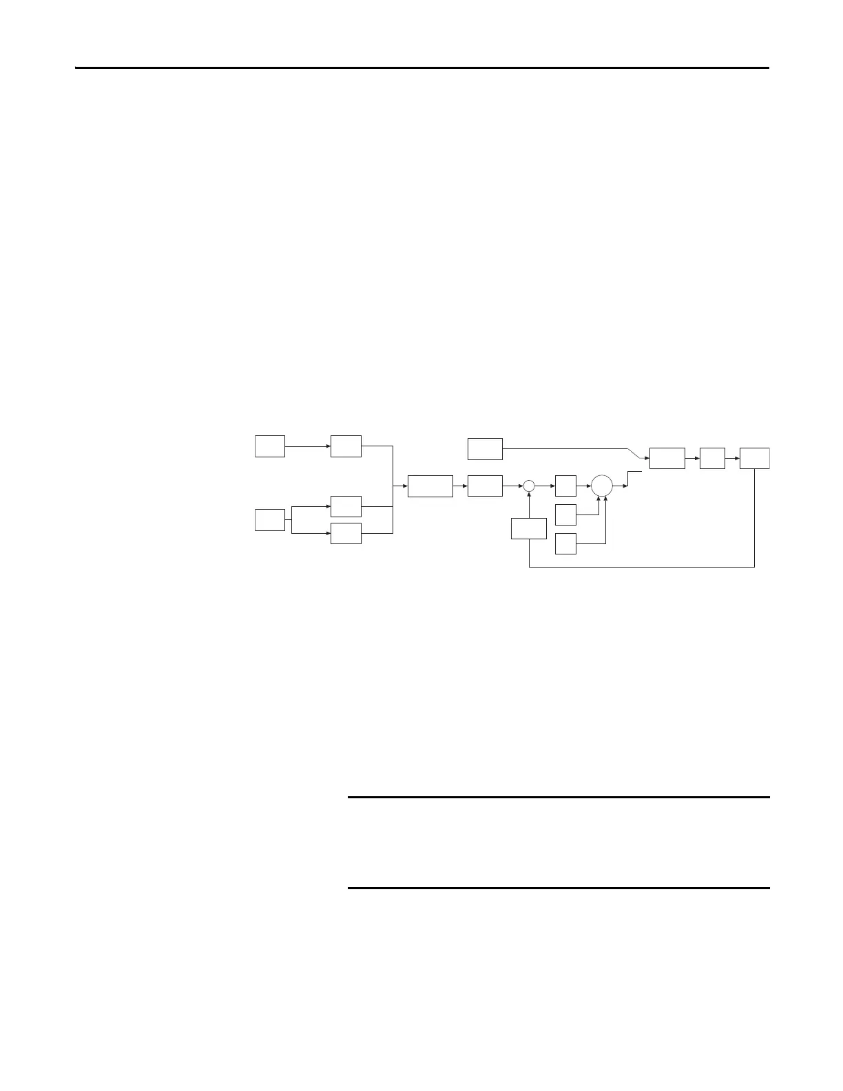
PID Function
This function allows you to control the production process and process feedback
signal to the drive to achieve PID process control.
To use the PID function:
1. Set PID Control Enable (P486) to “1”.
There is only the negative feedback function, there is no positive feedback
function.
2. Select the reference signal
If PID Control Enable is set to “1”, the frequency reference channel is
disabled and the PID reference channel is enabled. In the hardware, both
frequency reference and PID reference share the same channel.
3. PID reference signal
The drive PID digital and analog reference signals are shown in the
following diagram.
a. Digital reference signal
When the drive is in the Local control method (Owner #1 Selection
(P475) = “1”), the signal is provided by the HMI and the data range is
from 0...100.0.
When the drive is in the Remote control method (Owner #2 Selection
(P476) = “15”), the signal is provided by communications and the data
range is from 0...1000 (1000 = upper range limit * 10).
b. Analog reference signal
When the drive is in the Remote control method (Owner #2 Selection
(P476) = “8”), the signal is provided by the 4-20 mA input.
P475=0
P476=15
P476=8
0.0...100.0 PID Function Switch
Negative Feedback
0...1000
4-20 mA
HMI
Normalization
Comm
Analog
Local
Remote
P
I
D
Drive
PID
Reference
Frequency
Reference
Frequency
Reference
Control
Target
Feedback
Take note of the following:
• Failure during frequency-to-power conversion and power-to-
frequency conversion functions.
• Fault automatic conversion function is retained.

 Loading...


