18 Rockwell Automation Publication 6000-TD004D-EN-P - November 2017
Chapter 1 Functional Descriptions
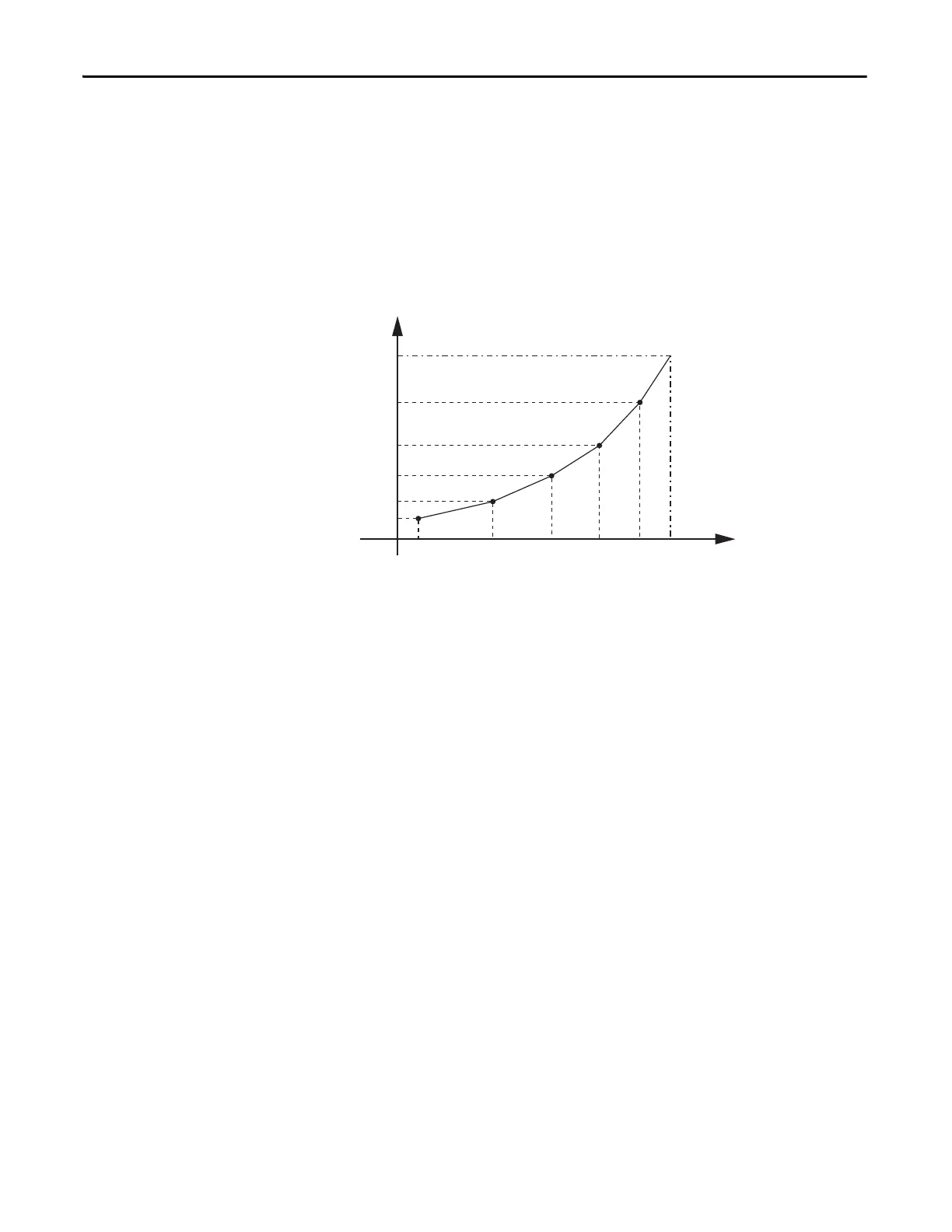
The voltage value for each of the five points should be set as follows:
V1 < V2 < V3 < V4 < V5
The voltage and frequency values for each of the five points should be set as
follows:
V1 < f1; V2 < f2; V3 < f3; V4 < f4; V5 < f5.
The relationship between the five points is shown in the diagram below.
Figure 2 - 5 Point VF Diagram
Digital Output
This function is used to set the digital output channel parameters. There are eight
digital output channels available in PowerFlex 6000 drives. The address, polarity,
and output delay time parameters can be adjusted according to the user’s
requirements.
For example, a user wants to configure a warning bell that is controlled through
the digital channel. This warning bell will go off when the digital channel output
voltage reaches a high level. Follow these steps below to configure the settings for
this example:
1. Set the address of the “warning bell” with parameter Digital Output #5
Memory Address (P320). The default value is “99”.
2. Enable this function by setting parameter Digital Output #5 Bit Selection
(P322) to “5” because this function corresponds to the position of Bit 5 of
K99.
3. Set the polarity with parameter Digital Output #5 Logic (P321). If you
want a high voltage level, set the value to “0”, else set the value to “1”.
4. If a one second signal delay is needed, set Digital Output #5 Delay (P323)
to “1000 ms”.
f1
V1
V2
V3
V4
V5
1
Voltage
Frequency
f2 f3 f4 f5 1

 Loading...


