Rockwell Automation Publication 6000-TD004D-EN-P - November 2017 23
Functional Descriptions Chapter 1
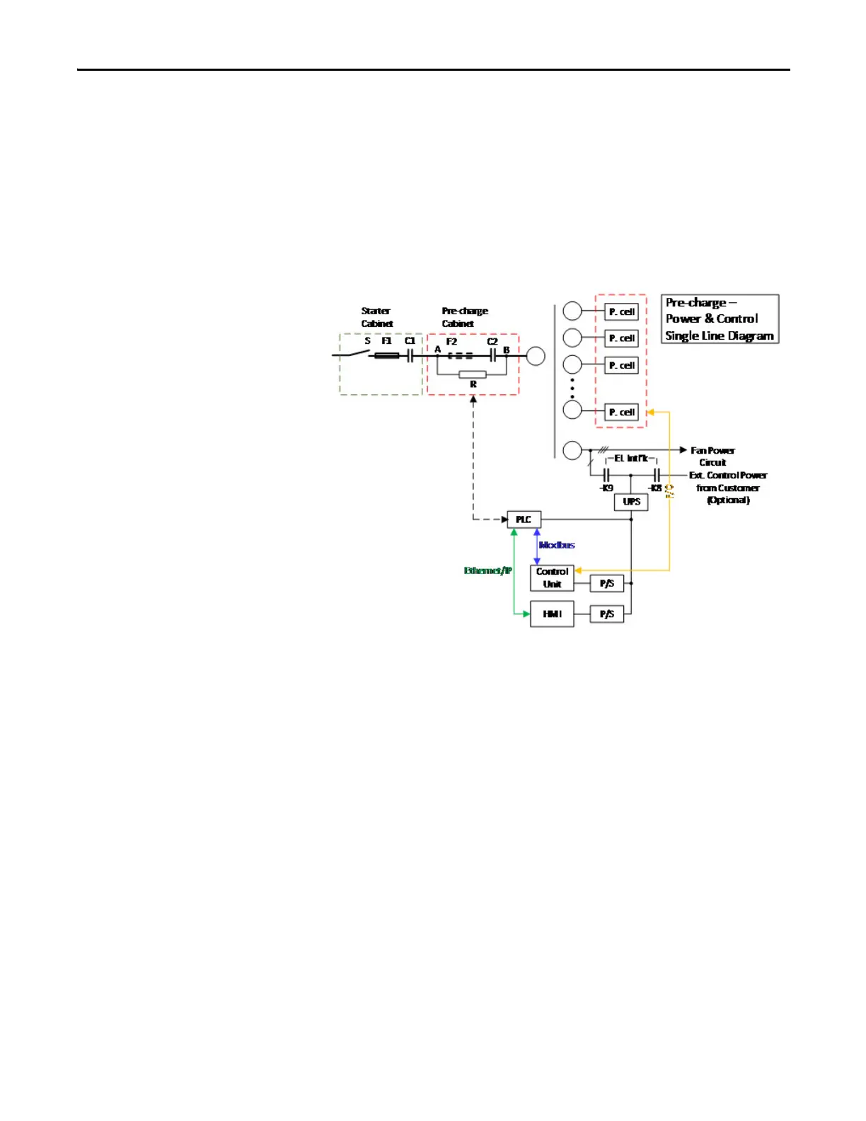
Pre-charge Control
The PowerFlex 6000 drive offers an optional pre-charge circuit on the primary
side of the transformer. The pre-charge circuit is used to magnetize the
transformer and to charge the power modules' DC bus capacitors with lower
current, thus avoid tripping the primary protection (fuse or circuit breaker) or
causing physical damage to the power component. The diagram of the pre-charge
circuit is shown below.
Figure 7 - Pre-charge Circuit Diagram
Set parameter Pre-charge Enable (P103) to “0” to disable or “1” to enable this
function. Parameter Pre-charge Feedback Delay (P104) is the feedback delay time
of the pre-charge contactor status. If there is no feedback from the pre-charge
cabinet within the time set in Pre-charge Feedback Delay, then the drive trips.
Parameters Pre-charge DC Bus Threshold (P105) and Pre-charge Primary Voltage
Threshold (P120) are used to provide feedback when the pre-charge is completed.
If the pre-charge process is not completed within the time set in parameter Pre-
charge Max Time (P118), the drive trips.
When the interval between two pre-charge process is less than the time set in
parameter Pre-charge Min Repeat Interval (P119), the drive trips.
When the line side voltage is less than parameter Pre-charge Resistor Short Circuit
Fault Threshold (P180) for a duration set in parameter Pre-charge Resistor Short
Circuit Fault Delay (P181), the drive trips.

 Loading...


